Heat pump with electric drive, 1 and 2-stage, brine/water heat pump: 20.5 to 84.6 kw, with conversion kit to water/water heat pump: 25.4 to 104.6 kw (92 pages)
Page 1
VIESMANN Installation and service instructions for contractors Vitocal 350-A Type AWHI 351.A Type AWHO 351.A 
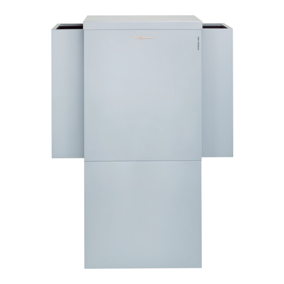
Air/water heat pump with electric drive, 400 V~ VITOCAL 350-A Please keep safe. 5692878 GB 11/2019...
Page 2
Safety instructions Safety instructions Please follow these safety instruc- tions closely to prevent accidents and material losses. Safety instructions explained Danger Note This symbol warns against the risk Details identified by the word "Note" of injury. contain additional information. Please note This symbol warns against the risk of material losses and environmen- tal pollution.
Page 3
Replace faulty components only been switched off. with genuine Viessmann spare Prior to removing covers from the parts. appliances, wait at least 4 minutes until the voltage has completely Auxiliary components, spare and dropped out.
Index Index 1. Information Disposal of packaging ................Symbols ....................Intended use ..................Product information ................System examples ................■ Spare parts lists .................. ■ 2. Installation preparations Requirements for on-site connections: Type AWHI 351.A ..... for heat pumps installed Cables/leads ..................
Page 5
Index Index (cont.) Power supply with power-OFF: Without on-site load disconnect ..66 ■ Power supply with power-OFF: With on-site load disconnect .... 66 ■ Phase monitor (if installed) ..............67 ■ Closing the heat pump ................69 Closing the control panel ..............70 ■...
Information Disposal of packaging Please dispose of packaging waste in line with statu- tory regulations. Symbols The steps in connection with commissioning, inspec- Symbol Meaning tion and maintenance are found in the "Commission- Reference to other document containing ing, inspection and maintenance" section and identified further information as follows: Step in a diagram:...
Product information Layout Central heating The Vitocal 350-A is an air source heat pump with out- The heat pump is able to supply up to 3 heating cir- put-dependent control. cuits: 1 heating circuit without mixer and 2 heating cir- Type AWHI 351.A is installed inside the building.
Installation preparations for heat pumps installed indoors Requirements for on-site connections: Type AWHI 351.A Fig. 1 Dimensions excluding casing panels: 790 mm x c Cable entries Condensate drain Heating water return/DHW cylinder return G 1 Heating water flow/DHW cylinder flow G 1 ½...
Installation preparations for heat pumps installed indoors Requirements for on-site connections: Type AWHI 351.A (cont.) Cables/leads Heating water buffer cylinder Secondary pump, power cable: 3 x 1.5 mm Heating circuit pump Buffer temperature sensor, sensor lead: 2 x 0.75 mm Required cable lengths: ■...
Page 10
Installation preparations for heat pumps installed indoors Requirements for transport and siting: Type AWHI 351.A (cont.) Please note Minimum room volume (to EN 378): Overloading the floor can result in damage to the building structure. AWHI 351.A10 13.55 m Observe the permissible floor load. Take the AWHI 351.A14 16.13 m total weight of the appliance into account.
Installation preparations for heat pumps installed indoors Requirements for transport and siting: Type AWHI 351.A (cont.) Minimum clearances and dimensions for corner installation Note Dim. Vitocal 350-A, type AWHI Before making the wall openings, check the struc- ■ 351.A10 351.A14 351.A20 tural analysis of the building and the wall.
Page 12
Wall clearances Discharge side on the left Discharge side on the right D E F Exterior rendering Dim. Vitocal 350-A, type AWHI Wall 351.A10 351.A14 351.A20 Wall duct (EPP, can be trimmed to the correct size from the outside with a saw. Observe plaster thick-...
Installation preparations for heat pumps installed indoors Requirements for transport and siting: Type AWHI 351.A (cont.) Minimum clearances and dimensions for wall installation Dimensions of wall openings Dim. Vitocal 350-A, type AWHI 351.A10 351.A14 351.A20 1020 1180 Fig. 4 Partition wall (if required): See table on pages...
Page 14
Appliance connector, air duct on the intake side Distance between wall openings inside the building (EPP) Distance between wall openings outside the build- Plaster finish/wall coating Dim. Vitocal 350-A, type AWHI 351.A10 351.A14 351.A20 1020 1180 Distances between wall openings X and Y in mm...
Page 15
Installation preparations for heat pumps installed indoors Requirements for transport and siting: Type AWHI 351.A (cont.) Partition wall Air intake/air discharge via weather grille Air intake/air discharge via light well ≥ 1 ≥ 1 Fig. 6 Discharge side Weather grille Partition wall Intake side Height to the top edge of the weather grille...
Installation preparations for heat pumps installed outdoors Requirements for on-site connections: Type AWHO 351.A Fig. 8 Condensate drain Heating water return G 1 (female thread): ¼ Heating water flow G 1 (female thread): Adaptor G 1 to Rp 1 supplied ¼...
Installation preparations for heat pumps installed outdoors Requirements for transport and siting: Type AWHO 351.A Transport The appliance can be lifted onto the foundations with, Please note for example, a crane and on-site equipment. Impacts, compression and tensile loads can cause damage to the outside panels of the Please note appliance.
Provide an adequately sized recess (see diagram Weight ■ below) in the foundations to permit the lines (heating Vitocal 350-A, type Weight (incl. silenc- water flow and return, cables and condensate drain) er hoods) to be brought into the heat pump from below.
Page 19
Installation preparations for heat pumps installed outdoors Foundations: Type AWHO 351.A (cont.) Plan view Fig. 10 Heat pump Soft ground, gravel or crushed stone Concrete foundations (300 mm thick) consisting of: Routing direction of pipe from hydraulic connection ■ Concrete slab C25/30, BSt 500 S and M set: Towards the front ■...
Page 20
Installation preparations for heat pumps installed outdoors Foundations: Type AWHO 351.A (cont.) Note Dim. Vitocal 350-A, type AWHO ■ Before laying the concrete foundations, trim the 351.A10 351.A14 351.A20 hydraulic connection pipes (heating water flow and 1080 1230 1400 return), install the connection fittings and provide frost protection.
Installation preparations for heat pumps installed outdoors Cables/leads and hydraulic lines: Type AWHO 351.A Laying cables/lines underground and routing in through the exterior wall Fig. 12 Concrete foundation (300 mm thick) consisting of: 2 connecting cables inside DN 100 KG conduit (on ■...
Page 22
KG conduit. mal insulation. ■ Cable length required in the heat pump from top edge of foundations: Min. 2.6 m. Vitocal 350-A, type AWHO 351.A20 ■ Flow/return lines: 2 x DN 40 Connecting cables Adaptors: DN 40 to R 1 ■...
Installation preparations for heat pumps installed outdoors Cables/leads and hydraulic lines: Type AWHO 351.A (cont.) Required cables and hydraulic lines Fig. 13 Heat pump Circulation pump for cylinder heating or 3-way Extra low voltage (ELV) lead, pre-manufactured diverter valve, power cable (3 x 1.5 mm Control cable, pre-manufactured DHW circulation pump, power cable (3 x 1.5 mm Flexible power cable for special tariff/load current:...
Installation sequence Removing the transport brackets Please note If transport brackets are not removed, they cause vibrations and excessive noise. Remove the transport brackets and replace the screws. Fig. 14...
Installation sequence Fitting the outer panels Installation using type AWHI 351.A as an example. Fig. 16 4. Only required for type AWHI 351.A...
Page 27
Installation sequence Fitting the outer panels (cont.) Installation of side panels with air discharge on the l.h. side (delivered condition for type AWHI 351.A) Fig. 17 5. Only required for type AWHI 351.A...
Page 28
Installation sequence Fitting the outer panels (cont.) Installation of side panels when air discharge is on the right Fig. 18 Note To facilitate installation, apply a soapy solution to the edges of the side panel insulation. 5. Only required for type AWHI 351.A...
Installation sequence Fitting the top panel Type AWHI 351.A Type AWHO 351.A Fig. 23 Fig. 22 Siting the heat pump Only type AWHI 351.A: Connecting the air circuit (primary circuit) See also installation information for siting on page 9 1. Centre the wall outlets in the wall cut-outs and onwards.
Page 33
Installation sequence Siting the heat pump (cont.) Fig. 24 Heat pump installed outdoors ■ Site the heat pump according to the details on page 17. ■ Secure the heat pump to the foundations.
Installation sequence Siting the heat pump (cont.) Fig. 25 If the adjustable feet are used to compensate for an uneven floor (max. 10 mm), distribute the pressure load on the feet evenly. Making the hydraulic connections Please note Please note Hydraulic connections subjected to mechanical Leaking hydraulic connections lead to appliance loads lead to leaks, vibrations and appliance...
Installation sequence Making the hydraulic connections (cont.) Information on the condensate drain ■ Subject to temperature and relative humidity, the vol- ume of condensate accumulating from the air can be as high as 20 litres/h. ■ During the defrosting process, the amount of con- densate can be as high as 20 litres within 5 min.
Installation sequence Making the hydraulic connections (cont.) Heat pump installed outdoors 1. Cut suitable openings on site in sealing mat Note If an instantaneous heating water heater is installed, fit hydraulic lines and condensate drain the flow temperature sensor for the secondary circuit in the heating water flow downstream of the instantane- ous heating water heater.
Installation sequence Electrical connections: Control panel Danger Danger Damaged wiring insulation wiring can lead to Incorrect wiring can lead to serious injury from serious injury from electrical current and result in electrical current and result in appliance dam- appliance damage. age.
Installation sequence Electrical connections: Control panel (cont.) Overview of electrical connections in the control panel Type AWHI/AWHO 351.A10, AWHI/AWHO 351.A14 Fig. 30 Type AWHI/AWHO 351.A20 Fig. 31 Fan fuse 6.3 A (slow) Mains terminals (400 V~) for compressor and fan Phase monitor with contact shield and power-OFF seal if required Compressor contactor...
Installation sequence Electrical connections: Control panel (cont.) Routing cables/leads to the control panel Danger Cable entry from the right Damaged cable insulation can cause injury and damage to the appliance. Route cables so that they cannot touch very hot, vibrating or sharp-edged components. Internal heat pump ¨...
Page 40
Installation sequence Electrical connections: Control panel (cont.) External heat pump 1. Internal heat pump: Route the 230 V cables through one cable entry, and the LV lead through the other cable entry in the l.h. or r.h. side panel. External heat pump: Cut one entry in the sealing mat for the 230 V cables and a second entry for the LV lead.
Installation sequence Electrical connections: Control panel (cont.) Attaching the connecting cables from the control unit in the control panel Fig. 35...
Page 43
Installation sequence Electrical connections: Control panel (cont.) < 42 V 230 V~ X14.6 Fig. 37 Cover panel Bracket Control cable 230 V~ Cable ties Extra low voltage (ELV) lead < 42 V...
Installation sequence Electrical connections: Heat pump control unit Fitting the heat pump control unit and inserting cables Wall mounting base and casing base, fitting Fig. 38...
Page 45
Installation sequence Electrical connections: Heat pump control unit (cont.) Fitting the casing front Fig. 39 Cross connect PCB Casing front ON/OFF switch plug-in connection Controller and sensor PCB...
Page 46
Installation sequence Electrical connections: Heat pump control unit (cont.) Heat pump control unit, open Fig. 40...
Page 47
Installation sequence Electrical connections: Heat pump control unit (cont.) Cables, inserting and applying strain relief Fig. 41 Cables with moulded strain relief On-site cables/leads...
Installation sequence Electrical connections: Heat pump control unit (cont.) Attaching cables from the control panel in the control unit Fig. 42 Cross connect PCB Connecting cable (LV lead < 42 V) Controller and sensor PCB Connecting cable (control cable 230 V~) Adjusting the heat pump control unit (red cores) The secondary pump and/or the instantaneous heating The red cores connect the following terminals: See...
Page 49
Installation sequence Electrical connections: Heat pump control unit (cont.) Fig. 43 Type AWHO 351.A Type AWHI 351.A: Secondary pump outside the heat pump Fig. 44 Fig. 45 Instantaneous heating water heater (accessories) Instantaneous heating water heater (accessories) Red wires to be removed (see fig. 43 on page 48) X6.6 211.2 Red wires to be removed (see fig.
Page 50
Installation sequence Electrical connections: Heat pump control unit (cont.) Type AWHI 351.A: Secondary pump inside the heat The following components are connected in the heat pump pump control unit (see page 51 onwards): ■ Circulation pump for cylinder heating The following components are connected in the heat pump control panel (see separate installation instruc- tions and page 37 onwards): On-site secondary pump: See the following chapter...
Installation sequence Electrical connections: Heat pump control unit (cont.) Inserting the coding card Only insert the coding card that comes supplied with the heat pump. Fig. 49 Coding card Controller and sensor PCB Overview of electrical connections Danger Danger Damaged wiring insulation wiring can lead to Incorrect wiring can lead to serious injury from serious injury from electrical current and result in electrical current and result in appliance dam-...
Installation sequence Electrical connections: Heat pump control unit (cont.) sYA sYS Fig. 50 Cross connect PCB: See page 58. Expansion PCB: See page 55. F1 Fuse 6.3 A (slow) Controller and sensor PCB: See page 58. X6 Red wires for matching the heat pump control unit to the system version (see page 48) Main PCB: See page 52.
Page 53
Installation sequence Electrical connections: Heat pump control unit (cont.) Plug Terminals Function Explanation 211.1 Connection values: Output: 200 W ■ Voltage: 230 V~ ■ Max. switching current: 4(2) A ■ 211.2 Secondary pump In systems without a heating water buffer cylinder, no ■...
Page 54
Installation sequence Electrical connections: Heat pump control unit (cont.) Connecting a temperature limiter as a maximum temperature limiter for underfloor heating Connecting a general temperature limiter Connecting the temperature limiter, part no. 7151728, X2.N 7151729 X2.N sÖ Fig. 51 Fig. 52 Connection to con- Circulation pump...
Installation sequence Electrical connections: Heat pump control unit (cont.) Expansion PCB on main PCB (operational components 230 V~) Information regarding the connection values Set the required parameters during commissioning; The specified output is the recommended connected see from page 78. ■...
Page 56
Installation sequence Electrical connections: Heat pump control unit (cont.) High limit safety cut-out for heat pump in conjunc- tion with external heat generator X3.1 222.3 222.4 X2.N Fig. 54 Terminals on extension PCB Connect jumper across X3.1 and 222.3. Connection on external heat generator to terminals for "External demand"...
Page 57
Installation sequence Electrical connections: Heat pump control unit (cont.) Plug Terminals Function Explanation 224.4 Instantaneous heating water heater Connection values: switching, stage 2 Output: 10 W ■ Voltage: 230 V~ ■ Max. switching current: 4(2) A ■ See installation instructions for "instantaneous heating water heater"...
Installation sequence Electrical connections: Heat pump control unit (cont.) Plug Terminals Function Explanation 225.1 Heating circuit pump of the heating Connect a temperature limiter to restrict the maximum circuit with mixer M2/HC2 temperature for underfloor heating circuits (if installed) in series. Connection values: Output: 100 W ■...
Page 59
Installation sequence Electrical connections: Heat pump control unit (cont.) Terminals Function Explanation X3.2 "External blocking" signal (external blocking Requires floating N/O contact: X3.14 of compressor and pumps, mixer in control Closed: Blocking enabled ■ or at external mode or CLOSE) Open: No blocking ■...
Installation sequence Electrical connections: Heat pump control unit (cont.) Terminals Function Explanation X3.10 Fault message, lag heat pump in a cas- Requires floating contact: X3.11 cade Closed: No faults ■ Open: Fault ■ Jumper Breaking capacity 230 V~, 0.15 A ■...
Page 61
Installation sequence Electrical connections: Heat pump control unit (cont.) Plug Sensors/terminals Type (PTC) System flow temperature sensor (with sensor well, downstream of Pt500 the heating water buffer cylinder) Boiler water temperature sensor, external heat generator Pt500 (X6.8/X6.9) KM-BUS Wires interchangeable; for several appliances, use the KM-BUS distributor (accessories).
Page 62
Installation sequence Electrical connections: Heat pump control unit (cont.) fÖ gÖ Fig. 57 Connection to controller and sensor PCB Fuses and contactor for circulation pump for swim- External H1 extension ming pool heating (accessories) Temperature controller for regulating swimming Circulation pump for swimming pool heating pool temperature (floating contact, 230 V~, 0.1 A, (accessories) accessories)
Page 63
Installation sequence Electrical connections: Heat pump control unit (cont.) X3.10 X3.11 230V 223.1 fÖ 223.2 230V 223.1 223.2 230V sÖ 223.1 223.2 Fig. 58 Heat pump 1 (lead heat pump) Lag heat pump 2 KM BUS Connection at contact for "External demand " External extension H1 Floating contact "External demand "...
Installation sequence Power supply Isolators for non-earthed conductors The assignment of the power-OFF (for compressor ■ ■ Install an isolator in the power cable to provide and/or instantaneous heating water heater) is made omnipolar separation from the mains for all active via the type of connection and by setting parameters conductors, corresponding to overvoltage category in the heat pump control unit.
Installation sequence Power supply (cont.) Information regarding the compressor power sup- ■ Please note An incorrect phase sequence can cause dam- age to the appliance. Make the compressor power supply only in the phase sequence specified (see terminals) with a clockwise rotating field. ■...
Installation sequence Power supply (cont.) 5. If a seal is required (e.g. when using an economy On-site fuse protection in accordance with the com- ■ tariff with power-OFF), pass the seal wire through pressor rating (see specification). the holes drilled in both studs. Note The upstream MCBs must have B characteristics.
Installation sequence Power supply (cont.) X3.7 X3.6 ≈ Fig. 62 Diagram excluding fuses and RCD Heat pump control unit Instantaneous heating water heater Compressor Economy tariff meter Feed: TNC system Backup fuse, ripple control receiver Ripple control receiver (contact open: Power-OFF enabled) Premium tariff meter Mains isolator...
Page 68
Installation sequence Power supply (cont.) Version 1 Version 2 N 11 21 <>U <>U L1 L2 L3 12 14 22 24 Fig. 64 LEDs explained in Fig. 64 Fig. 63 Voltage "U": ■ Illuminates green if voltage is present. Over/undervoltage in % Relay "R": Phase asymmetry in % ■...
Installation sequence Power supply (cont.) Version 3 LEDs explained in Fig. 65 Voltage "Un": ■ Illuminates green if voltage is present. Relay "R": ■ Illuminates yellow if the phase sequence is cor- rect. L1, L2, L3 Does not illuminate if the phase sequence is ■...
Installation sequence Closing the heat pump (cont.) Closing the control panel Fig. 66 Holes for type AWHI/AWHO 351.A120 Holes for type AWHI/AWHO 351.A114 Holes for type AWHI/AWHO 351.A110...
Commissioning, inspection, maintenance Opening the heat pump Danger Please note Contact with live components can lead to seri- Refrigerant can escape when working on the ous injury from electric current. refrigerant circuit. ■ Do not touch the connections in the control Work on the refrigerant circuit must only be car- panel (see chapter "Overview of connections ried out by a certified contractor (in accordance...
Commissioning, inspection, maintenance Opening the heat pump (cont.) Pivoting control panel to the side Fig. 68 Compiling reports Enter the readings taken during commissioning (described hereafter) into the reports on page 87 onwards. Checking the refrigerant circuit for leaks Danger Danger The refrigerant is a non-poisonous gas that dis- Direct contact with refrigerant can be harmful to...
Commissioning, inspection, maintenance Checking the refrigerant circuit for leaks (cont.) Please note Check the floor area, valves and all visible solder joints Refrigerant can escape when working on the for traces of oil. refrigerant circuit. Work on the refrigerant circuit must only be car- Note ried out by a certified contractor (in accordance Traces of oil indicate a leak in the refrigerant circuit.
Commissioning, inspection, maintenance Filling and venting on the secondary side (cont.) 3. Fill the secondary circuit via the on-site BDF valve 6. Close drain & fill valve. (flush) and vent the circuit. 7. Connect on-site hose to manual air vent valve 4.
Commissioning, inspection, maintenance Cleaning the interior (cont.) Fig. 70 Condensate drain Interior 4. Clean the interior with a vacuum cleaner first and 6. Assembly: Steps 1 to 3 in reverse order then with a hand shower. If necessary, wipe dry with a soft cloth.
2. Measure the temperature of the compressor casing exterior while it is in operation. The compressor must not develop a layer of ice on its outside, and the casing must not get hotter than C (if necessary, check with Viessmann techni- ° cal service). Commissioning the system...
Page 79
Commissioning, inspection, maintenance Commissioning the system (cont.) Language Date/Time Time Date Start commissioning? Coding Parameter group Parameters level 1 select Temperature Sensor values sensors display Signal inputs Signal inputs display Actuator test Actuator test carry out Subscriber check (LON) Subscriber check carry out Function check Function...
Page 80
Commissioning, inspection, maintenance Commissioning the system (cont.) 2. "Service" 5. Select parameter: "System scheme 7000" 3. Select "Coding level 1". 6. Set a system scheme: e.g. "6" 4. Select parameter group: "System definition" Required parameters for components connected on site Detailed explanation of parameters Overview of possible system schemes "Vitotronic 200"...
Page 81
Commissioning, inspection, maintenance Commissioning the system (cont.) Pump/component Parameter Setting Heating circuit pump and mixer M3 "System definition" With heating circuit with mixer Ó (controlled via mixer extension kit) "System scheme 7000" Note Set rotary switch S1 in the ex- tension kit to "2"...
Page 82
Commissioning, inspection, maintenance Commissioning the system (cont.) External functions External function Parameter Setting External demand If applicable "Internal hydraulics" Set flow temperature for ex- Ó "Flow temperature for external de- ternal demand mand 730C" External starting of the compressor; "System definition" "0"...
Page 83
Commissioning, inspection, maintenance Commissioning the system (cont.) Enable external heat source for DHW heating Parameter Setting "External heat source" Ó "Enable external heat source for DHW heating 7B0D" "1" Parameters for immersion heater Parameters Setting "DHW" Ó "Enable electric heaters for DHW heating 6015" "1"...
Commissioning, inspection, maintenance Commissioning the system (cont.) Parameter Setting Lead heat pump Lag heat pump "System definition" "0" to "255" – Ó "Output lag heat pump 700B" "System definition" "0" to "31" "0" to "31" Ó "Use of heat pump in cascade 700C" ≙...
Troubleshooting Repairs Overview of sensors, drain and air vent valves Fig. 73 Refrigerant receiver Safety high pressure switch Drain valve Electronic expansion valve (EEV) Secondary circuit return temperature sensor Manual air vent valve Thermostatic expansion valve 4-way diverter valve Temperature sensor EVI High pressure sensor Solenoid valve Hot gas temperature sensor...
Troubleshooting Repairs (cont.) Sensor Test element Outside temperature sensor (F0) Ni500 ■ Flow temperature sensor, heating circuits M2 (F12) ■ System flow temperature sensor (F13) Pt500 ■ Buffer temperature sensor (F4) ■ Cylinder temperature sensor, top/bottom (F6/F7) ■ Flow/return temperature sensor, secondary circuit (F8/F9) ■...
Commissioning/service reports Hydraulic parameter report Settings and test values Set value Commissioning Maintenance/ service Checking external heating circuit pumps Circulation pump type Circulation pump stage Overflow valve setting Commissioning, primary circuit Air intake temperature °C ("Diagnosis" "System overview") Ó Air discharge temperature °C ("Diagnosis"...
Page 88
Commissioning/service reports Control parameter report (cont.) Parameter Code Factory setting Commission- Operating status for external changeover 7012 Effect of external blocking on pumps/compressor 701A Duration of external changeover 7013 Effect of external demand on heat pump/heating cir- 7014 cuits Effect of ext. blocking on heat pump/heating circuits 7015 Vitocom 100 7017...
Page 89
Commissioning/service reports Control parameter report (cont.) Electric booster heater Parameter Code Factory setting Commission- Enable instantaneous heating water heater 7900 Enable instant. heating water heater for central heating 7902 Max. output instantaneous heating water heater 7907 Output for instant. heating water heater at power-OFF 790A ≙...
Page 90
Commissioning/service reports Control parameter report (cont.) Parameter Code Factory setting Commission- Influence room temperature hook-up 300A Room temperature hook-up 300B ≙ Max. flow temperature heating circuit 300E 400 ( 40 °C) ≙ Room temperature in party mode 3022 160 ( 16 °C) Heating circuit 3 Parameter...
Specification Sound transmission data Type AWHI 351.A (heat pumps installed indoors, 400 V appliances) Type AWHI 351.A10 351.A14 351.A20 Siting Indoors Indoors Indoors Sound power level L A-weighted total sound power level in heating mode at ± /W35 ± , corner installation Inside installation room Fan stage 1 dB(A)
Appendix Heat pump commissioning order Please send the following order, together with the enclosed system scheme, by fax to your local Viessmann sales office. We would ask that a competent employee of yours be present during commissioning. System details: Client...
The product characteristics determined as system values for the product Vitocal 350-A (see technical guide) can be utilised to assess the energy consumption of heating and ventilation systems to DIN V 4701-10 specified...
Need help?
Do you have a question about the VITOCAL 350-A and is the answer not in the manual?
Questions and answers