
Related Manuals for Viessmann VITOTROL 350


Summary of Contents for Viessmann VITOTROL 350
- Page 1 Viesmann Operating instructions for the system user Remote control unit VITOTROL 350 Please keep safe. 5677 786 GB 3/2015...
- Page 2 Safety instructions For your safety Please follow these safety instructions closely to ■ Never remove casings. prevent accidents and material losses. ■ Never change or remove attachments or fitted accessories. Safety instructions explained Never open or retighten pipe connections. ■ Danger Danger This symbol warns against the risk of injury.
- Page 3 Safety instructions For your safety (cont.) In case of water leaking from the appliance Extractors Danger The operation of appliances that extract air to the out- Water leaking from the appliance poses an elec- side (cooker hoods, extractors, air conditioning units, trocution hazard.
- Page 4 Index Index 1. Introductory information Symbols ....................Terminology ................... Intended use ..................Commissioning ..................Permissible ambient temperature ............■ Energy saving tips ................. Tips for greater comfort ................. Central heating ................... ■ DHW heating ..................■ 2. Operation Controls and symbols ................Programming unit default display ............
- Page 5 Index Index (cont.) 6. Local heating network Local heating network supply ..............29 supply Changing the flow temperature of the local heating network supply ..29 Setting the holiday program for the local heating network supply ..29 7. Further adjustments Display settings ..................
- Page 6 Introductory information Symbols Symbol Meaning Reference to other document containing further information Step in a diagram: The numbers correspond to the order in which the steps are carried out. Warning of material losses and environ- mental pollution Live electrical area Pay particular attention.
- Page 7 These functions are not specifically The Vitotrol 350 can control up to 20 different circuits. identified. At the factory these circuits are each designated as a Check with your heating contractor should you have "Regulated circuit".
- Page 8 Introductory information Tips for greater comfort Central heating Standard room temperature ("Set room tempera- Heating curve ■ ■ ture") The heating curve enables you to individually adjust In the standard menu you can set your particular the heating system to the actual heat demand in your feel-good temperature at any time.
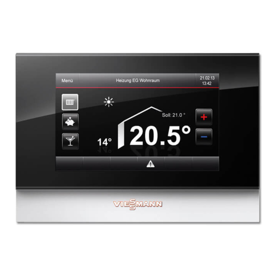
- Page 9 Buttons for temperature corrections Buttons for operating program Footer Bright background = active operating program The Vitotrol 350 programming unit is equipped with a touch sensitive display. To make adjustments and scan information, tap the on-screen buttons. Symbols in the display...
- Page 10 Operation Controls and symbols (cont.) Screensaver The following will be displayed: ■ Date 08:37 Time ■ Outside temperature ■ Wednesday Thursday Friday ■ Default display heating circuit room temperature 21/05/2014 Tap the display to reach the default display (see page 9). 23.4°C -3°...
-
Page 11: Table Of Contents
Operation User prompts (cont.) Menu Menu Local htg. ntwrk suppl. Boiler operation Heating Manual Information Settings Fig.4 Fig.5 "Boiler operation" see page 24 ■ "Heating" see page 12 ■ ■ "DHW" see page 21 ■ "Local heating network supply" see page 29 ■... -
Page 12: Heating
Central heating Central heating settings If you require central heating, check the following ■ Have you selected the correct operating program? points: ■ Have you selected the required time program? Have you selected the heating circuit? ■ For settings see chapter "Selecting the heating cir- cuit". - Page 13 Central heating Setting central heating temperatures (cont.) 5. +/- for the required temperature 6. Press "OK" to confirm Operating program Further information can be found in chapter "Terminology" in the appendix. Setting the operating program Default display Note 1. "Menu" Tapping è...
- Page 14 Central heating Time program (cont.) ■ For central heating, up to 4 changes per day 6. Select the time phase you want to change. between standard and reduced room temperature Phase 1 heating prog for Monday can be programmed (4 time phases). 00:00 For weekdays, time phase has been factory-set...
- Page 15 Central heating Comfort function "Party mode" (cont.) 4. "Op mode" 6. Set the required room temperature for "Party An operating program with a bright background is mode". already enabled. 7. Press "OK" to confirm 5. If "Party mode" is disabled, tap "Party mode". Note Heating mode must be switched on in order to...
- Page 16 Central heating Energy saving function "Holiday program" (cont.) 5. Set the required departure and return dates. The holiday program has the following effect: Rooms are heated to the set reduced room tempera- Holiday program ture (see page 12). from 2014 2014 Fig.14 6.
- Page 17 Central heating Heating curve (cont.) 5. "Temp level questionnaire" Temp level questionnaire Adjusting sensitivity -10°C cold How do you perceive the room temp 0°C when the outside temp cold is...? +10°C cold Fig.16 6. Make the required corrections. 7. Press "OK" to confirm Note Your input automatically changes the heating curve.
- Page 18 Central heating Heating curve (cont.) 6. Tap the required temperature button. Temperature level diagram Flow temperature curve setting Temperature level × °C -10° 0° 10° At an outside temp of ... Contractor mode Fig.19 7. Correct the temperature with the +/- buttons. 8.
- Page 19 Central heating Heating curve (cont.) 7. Tap the "Slope" or "Level" buttons. Temperature level diagram Flow temperature curve setting Slope Level 70° 57° 48° 40° 30° 25° °C -30° -20° -10° 0° 10° 20° At an outside temp of ... Standard Standard values...
- Page 20 Central heating Heating curve (cont.) ■ Heating curve level = 0 Different level settings shift the curve in parallel in a vertical direction. Standard room temperature = approx. 20 °C ■ In the delivered condition, the control unit has been programmed as follows: ■...
-
Page 21: Dhw
DHW heating Settings for DHW heating If you want DHW heating, check the following points: ■ Have you selected the required groups? Have you selected the required set DHW tempera- ■ ture? ■ Have you selected the required time program? DHW temperatures Changing the set DHW temperature Factory setting: 60 °C... - Page 22 DHW heating Individual time program Default display 7. Select the time phase you want to change. 1. "Menu" Phase 1 heating prog for Monday 2. "DHW" 00:00 3. Select the required group if there are several. 4. "DHW time program" from 12:00 DHW time program...
- Page 23 DHW heating Operating status for DHW heating (cont.) 3. Select the required group if there are several. An operating program with a bright background is already enabled. DHW on top floor Time program DHW mode Temperature Fig.30 4. If "DHW mode" is disabled, tap "DHW mode". 5.
-
Page 24: Boiler Operation
Boiler operation Boiler menu Overview display for manually charged boilers 21/05/2014 21/05/2014 Menu Use residual boiler heat Menu Use residual boiler heat 11:35 11:35 Oxy- Buffer Flow Flue gas fan Add boiler Ignition system cylinder temp Flue gas temp °C 26°C Details Details... - Page 25 Boiler operation Boiler menu (cont.) Call up overview Default display 3. Call up the required overview page with / . 1. "Menu" 4. Select the required menu. 2. "Boiler operation" 21/05/2014 Menu Use residual boiler heat 11:35 Oxy- Buffer Flow cylinder Flue gas temp 26°C...
- Page 26 Boiler operation Boiler menu (cont.) Flow display Display of the heating water buffer cylinder for manually charged boilers Flow Buffer cylinder Flow Return Buffer (°C) 10:00 Flow control 85° Sunday Monday Tuesday 85° 01/01/1970 81 °C 60 °C 100 % Set: 85 °C Set: 0 °C 40°...
- Page 27 Boiler operation Boiler menu (cont.) Flue gas fan display Setting the ignition system switching times Boiler operation Flue gas fan 1. With to the next overview screen 2. "Ignition system" Flue gas Flue gas temperature Heating prog, central heating 00:00 12:00 25 °C max.
- Page 28 Boiler operation Boiler menu (cont.) Fuel display Fuel Feed Blocking times vacuum module max. 90 % Fig.49 The following will be displayed: ■ Feed rate in percent ■ Suction module blocking time Display of the default output Default output Output default max.
-
Page 29: Local Heating Network Supply
Local heating network supply Local heating network supply A local heating network supply bridges the distance to regulated circuits that are further afield, for example in a neighbouring property. Several regulated circuits can be assigned to a local heating network supply, such as central heating and DHW heating of the neighbouring property. - Page 30 Local heating network supply Setting the holiday program for the local… (cont.) Rooms are heated to the set reduced room tempera- ture (see page 12).
- Page 31 Further adjustments Display settings Setting the background brightness You would like to see the text in the menu better. For 4. "Background illumination" this change the background brightness of the display. 5. Select the required backlight intensity. 6. Press "OK" to confirm Default display 1.
- Page 32 Further adjustments Display settings (cont.) 4. "Standby illumination" 5. "Panel switched off in standby" 6. Press "OK" to confirm Disabling the display briefly You can briefly lock the display, in order to clean the 4. "Locking the screen" surface for example. The message "Screen locked for cleaning"...
- Page 33 Further adjustments Display settings (cont.) 3. "Panel" 4. "Idle screen delay" 5. Select the required setting. Panel 6. Press "OK" to confirm Screen Illumination Illumination background standby lock Standby Idle screen delay delay Fig.58 Setting the time and date Default display 3.
- Page 34 Further adjustments Reinstating factory settings (cont.) Note If the heating/cooling circuits have been named, such names will be retained. Changing network settings Default display Further information can be found in chapter 1. "Menu" "Terminology" in the appendix. 2. "Settings" 3. "WWW" 4.
-
Page 35: Information
Scanning Scanning information You can call up "Information" if you require additional Default display details. 1. "Menu" 2. "Information" 3. Select the required group. Scanning fault message Symbol in the display footer will be shown in red if 3. You can acknowledge the cause of the fault with your heating system develops a fault. - Page 36 Appendix Terminology System version Reduced heating mode The system version describes the components of your For periods when you will be absent or during the heating system, such as a boiler, heating circuit pump, night, heat your home to the reduced room tempera- mixer, valves, control unit, radiators, etc.
- Page 37 Appendix Terminology (cont.) Heating curve slope Outside temperature in °C Fig.63 Setting of slope and level using the heating curve as an example The illustrated heating curves apply with the following settings: Heating curve level = 0 ■ ■ Standard room temperature (set value) = 20 °C Slope Outside temperature in °C Fig.64...
- Page 38 The cuits, if required. boiler control unit adjusts the heating circuit flow tem- The Vitotrol 350 enables up to 20 heating circuits to perature to various conditions by means of a mixer, for be controlled ("Heating circuit 1", "Heating circuit example when the outside temperature changes.
- Page 39 For example, the operating states for central heating ted circuits can be named individually. are differentiated according to their different tempera- The Vitotrol 350 enables the control of up to 20 regu- ture levels. lated circuits. The times at which the operating status changes are specified by you in the time program.
- Page 40 Appendix Information on disposal (cont.) Final decommissioning and disposal of the heating system Viessmann products can be recycled. Components and fluids from your heating systems are not part of ordinary domestic waste. Please contact your heating contractor in connection with the correct disposal of your old system.
- Page 41 Keyword index Keyword index Heating curve Ambient temperature............7 – Explanation............19, 36 – Level, changing............19 – Slope, changing............19 Boiler operation symbols..........25 Heating curve/cooling curve Booster heater – Comfort..............8 – Explanation............. 36 Heating curve slope/level........... 36 Heating mode –...
- Page 42 Keyword index Keyword index (cont.) Room temperature Time phases – Comfort..............8 – Central heating............13 – Reduced..............38 Time program Room temperature-dependent........36 – Central heating............13 – Comfort..............8 – Explanation............. 39 Screensaver..............9 Time setting..............33 Setting Tips – Holiday program............15 –...
- Page 44 Your contact Contact your local contractor if you have any questions regarding the maintenance and repair of your system. You may, for example, find local contractors on the internet under www.viessmann.com. Viessmann Werke GmbH&Co KG Viessmann Limited D-35107 Allendorf Hortonwood 30, Telford...
Need help?
Do you have a question about the VITOTROL 350 and is the answer not in the manual?
Questions and answers