Table of Contents
Advertisement
Advertisement
Table of Contents

Related Manuals for Volvo KAD44P


Summary of Contents for Volvo KAD44P
- Page 1 INSTRUCTION BOOK KAD44P, KAMD44P...
- Page 3 Welcome aboard Congratulations on your new boat and your choice of a Volvo Penta marine engine. A choice that will give you many years of boating pleasure. Your new marine engine is the result of more than 90 years experience in marine en-...
-
Page 4: Table Of Contents
Cooling system ............37 Fuel system ............42 Electrical system ........... 44 Reverse gear ............49 Drive ..............51 Steering ..............56 Propellers ............... 59 © 1997 AB VOLVO PENTA All rights to changes or modifications reserved. Printed on environmentally-friendly paper... -
Page 5: Safety Precautions
Read the Instruction Manual carefully before operating or servicing the engine. If anything is unclear please contact your Volvo Penta dealer for assistance. This symbol is used in the book and on the engine to make you aware of safety information. - Page 6 Safety precautions to be taken when operating the boat Your new boat Refueling Read Instruction Manuals and other information sup- When refueling there is always a danger of fire and plied with your new boat. Learn to operate the engine, explosion.
- Page 7 Carbon monoxide poisoning Most modern boats are designed in such a way that problems with backwash are extremely unusual. When a boat is moving forward backwash is caused Should a backwash problem occur do not open behind the boat. Sometimes this backwash can be so hatches or valves in the forward part of the boat.
- Page 8 Never carry out any work on the engine if you are un- flammable. Read and follow the instructions on the sure of how it should be done, contact your Volvo packaging. Penta dealer who will be glad to offer assistance.
- Page 9 Hot surfaces and fluids Lubrication system There is always a risk of burns when working with a Hot oil can cause burns. Avoid skin contact with hot hot engine. Beware of hot surfaces. For example: the oil. Ensure that the lubrication system is not under exhaust pipe, Turbo unit, oil pan, charge air pipe, pressure before commencing work on it.
-
Page 10: Introduction
Introduction This Instruction Manual has been compiled to help you get the most from your Volvo Penta engine. It contains all the information you need in order to operate and maintain your engine safely and correctly. Please read the In- struction Manual carefully and learn how to operate the engine, controls and other equipment safely. -
Page 11: Warranty And Guarantee Information
Warranty and Service book. Note that AB Volvo Penta’s liability is limited to that contained in the Warranty and Service Book. Read this book as soon as you take delivery of the engine. It contains important information about warranty cards, service and maintenance which you, the owner, must be aware of, check and carry out. -
Page 12: Presentation
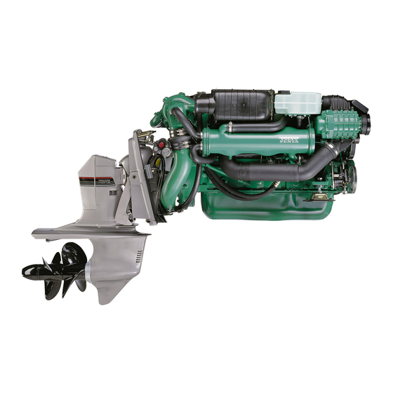
The Electronic Diesel Control system (EDC) also includes electronically controlled shifting for more precise and qui- eter shifting. The propulsion system shifting is performed by an electronic actuator integrated into the system. * EDC = Electronic Diesel Control. 15 16 KAD44P EDC/DP-E KAD44P EDC/DP-E... - Page 13 KAD44P EDC/DPX 12 11 KAMD44P EDC/HS1E 9. Cooling water intake 17. Compressor 1. Seawater filter 10. Corrosion protection 2. Terminal box 18. Trim cylinders 11. Fuel pump 3. Filling engine oil 19. Oil filter, reverse gear. 12. Fuel filter 4. Electronic control module 20.
-
Page 14: Identification Number
Identification number Your engine and transmission has identification plates with identification numbers. This information should al- ways be quoted when ordering service and replacement parts. There are probably similar plates on your boat and its equipment. Make a note of the details below, make a copy of the page and keep it so that you have a copy should the boat be stolen. -
Page 15: Instrumentation
Instrumentation This section contains descriptions of the instrument panels and panels available from Volvo Penta for your en- gine, with the exception of the Power Trim instrument, which is described in the section Power Trim. Note that the tachometer, oil pressure gauge, temperature gauge, charge indicator, ignition switch etc. which are shown here installed in the instrument panels can be installed in other positions on some boats. - Page 16 Control panel with ignition switch Master control position panel 1. Siren for acoustic alarm. 2. Switch for instrument lighting. 3. Alarm test/acknowledgment switch.* 4. Key switch.* * See description on page 15. Control panel without ignition switch Panel for Flying Bridge (alternative operating posi- tion).
- Page 17 Warning display If the acoustic alarm sounds, one of the three warning lamps (1–3) on the instrument panel starts to flash to indicate the source of the alarm. 1. Engine coolant temperature too high. 2. Low oil pressure. 3. Generator not charging. 4.
- Page 18 Control panel Various functions can be selected from the control panel. The required function is activated or deacti- vated by pressing the appropriate button. The buttons have integral lamps which indicate the selection and NEUTRAL DIAGNOSIS status of a particular function. There are three different types of control panel, which one(s) are installed depends on the number of engines and control positions on the boat.
-
Page 19: Controls
Controls This chapter describes the Volvo Penta control systems available for your Volvo Penta engine. Two of them are electronic and the third is mechanical. All have a shift function and engine speed control combined in the same lever where the shift function can be disengaged so only the engine speed is affected. - Page 20 Disengaging the shift function. Mechanical controls Move lever (1) to the neutral position (N). Press in button (2), move the lever slightly forward and release the button. The shift function is now disengaged and the lever affects only engine speed. When the lever is moved back to the neutral position it will auto- matically re-engage.
-
Page 21: Power Trim
Power Trim Your Volvo Penta propulsion system is equipped with a Power Trim hydraulic trim system which makes it possi- ble to adjust the angle of the drive in relation to the stern of the boat. This adjusts the boat’s trim to obtain maxi- mum comfort and fuel economy in different operating conditions. - Page 22 Lift range The lift range is used for lifting the drive to its maximum angle, how- ever this cannot be used during normal operation of the boat. The range is used mainly for trailer transport of the boat. The Power Trim has an automatic stop which cuts off the current when the stop position is reached.
- Page 23 Analogue trim instrument (DP) The trim instrument indicates the current trim position of the drive. The scale has five calibration points with the Beach and Lift range marked in red. 1. Trim range 2. Beach range (red). 3. Lift range (red) Trim instrument (DPX) The instrument shows the current position of the drive within the Trim range and the beginning of the Beach range.
-
Page 24: Starting The Engine
Starting the engine Make a habit of checking the engine and engine compartment visually before operating the boat. This will help you to quickly detect anything unusual that has or is about to happen. Also check that instruments and the warn- ing display are indicating normal values when you have started the engine. - Page 25 3. Turn the key to position “III” to start. Release the key as soon as the engine has started, the key will automatically return to the “I” position. If the engine did not start the key must first be turned to the “0”...
-
Page 26: Operation
Driving It is important to learn how to operate the engine, controls and other equipment safely and properly before setting off on a maiden voyage. Avoid violent and unexpected changes in course and gear engagement. There is a risk that someone aboard will fall over or overboard. WARNING! A rotating propeller can cause serious injury. - Page 27 Maneuvering Only shift between forward and astern at engine idle speed as shifting at higher engine speeds can cause discomfort for those on board and unnecessary strain on the drive/reverse gear or the engine to stop. Attempting to shift when the engine speed is too high will automatically result in the shift being delayed until the engine speed drops to approx- imately 1,000 rpm.
-
Page 28: Cruising Speed
Cruising speed Operating the engine at maximum RPM should be avoided since it is both uneconomical and uncomfortable. Volvo Penta recommends a cruising speed approximately 200 rpm lower than maximum rpm at wide open throttle (WOT). Depending on hull type, choice of propeller, load and conditions etc. -
Page 29: Power Trim
Power Trim while running The Power Trim adjusts the drive angle to the stern of the boat to ob- tain maximum comfort and fuel economy at different speeds, with varying loads, and in a range of wind and sea conditions. Power Trim settings and adjustment are controlled from the helm po- sition using the controls and instruments described in the Power Trim section. - Page 30 If this is the case or if other damage has occurred to the drive it must be inspected at an au- thorized Volvo Penta workshop. If only the propeller has been dam- aged it must be replaced. Launch the boat and test drive. If there are still vibrations it must be inspected by an authorized Volvo Penta workshop.
-
Page 31: Stopping The Engine
Stopping the engine The engine should be run for a few minutes at idle (in neutral) before turning it off. This will avoid boiling and even out the temperature. This is especially important if the engine has been operated at high engine speeds and loads. -
Page 32: Cold Weather Precautions
Cold weather precautions To prevent freezing damage, the seawater system must be drained and the freshwater system coolant must have sufficient antifreeze protec- tion. Refer to the section on the cooling system in “Care”. IMPORTANT! A poorly charged battery may burst as a result of freezing. -
Page 33: Maintenance Schedule
Maintenance schedule Your Volvo Penta engine and its transmission is designed for maximum service life and reliability. They are built to survive in a tough marine environment, but also to cause as little environmental impact as possible. Regular main- tenance according to the following schedule is necessary if the engine and transmission are to operate without problems. -
Page 34: Maintenance And Care
Maintenance and care This chapter describes how to carry out the above maintenance. Read the instructions carefully before starting work. Maintenance intervals are contained in the chapter above: Maintenance schedule WARNING! Read the safety precautions for maintenance and service in the chapter: Safety Precautions, before starting work. - Page 35 Exhaust system. Check The exhaust system in the drive installations must be checked every year for corrosion damage between hose (1) and the pipe (2). WARNING! Risk of water penetration. Checking the exhaust system should be carried out with the boat on land. If there is heavy corrosion the pipe should be re- paired or replaced with a new one.
- Page 36 2. Generator belt Undo the generator mounting bolts (1) and (2). Tight- en belt using the adjuster screw (3) so the belt can be depressed approximately 10 mm between the belt pulleys at (B). Tighten bolts (1) and (2). 3. Compressor belt Remove the belt cover.
- Page 37 Controls, engine idling speed (rpm) adjustment The engine idle speed is adjusted at the factory to 600 rpm. If required the idle speed can be adjusted within the range 600–700 rpm. Note. Adjustments can only be made from the Mas- ter control position*.
-
Page 38: Lubrication System
Lubrication system IMPORTANT! With a new or reconditioned engine, the oil and oil filters must be changed after 20–50 hours of operation. After that they should be changed every 100 operating hours or at least once a year. Use only the recommended grades of oil: See the chapter “Technical Data”. -
Page 39: Cooling System
There should be at least 40% antifreeze in the sys- tem for complete protection against corrosion. Where there is no risk of damage from freezing the engine coolant can be fresh water with of Volvo Penta anti-corrosion fluid added. Mix according to the in- structions on the packaging. - Page 40 Coolant. Changing The corrosion-proofing additives become less effec- tive with time and the coolant must be changed. If the freshwater system is filled with antifreeze mixture it must be changed every other year. If the system is filled with anti-corrosion agent mixture it must be changed every year.
- Page 41 Seawater system. Draining To prevent freezing damage the seawater system must be drained in cold weather where there is a risk of frost. WARNING! If the boat is left in the water, the seawater intake to the engine must be turned off with a seawater cock (non-standard equipment) or other method before draining the engine.
- Page 42 Seawater system. Cleaning and inhibiting To prevent the build up of deposits and salt crystals in the seawater system it must be flushed with freshwa- ter. When the boat is laid up it must also be inhibited. WARNING! Risk of water penetration. Cleaning and inhibiting the seawater system should be carried out with the boat on land.
- Page 43 Impeller. Checking/Replacing WARNING! Risk for water penetration. If the boat is in the water the following measures should be carried out before starting work: Re- verse gear: Close the sea cock. Remove the cover from the seawater pump and re- move the impeller (1).
-
Page 44: Fuel System
Fuel system All work on the engine injection pump or injectors must be carried out at an authorized workshop. Use only the recommended grade of fuel: See the chapter “Technical Data”. WARNING! Fire risk. When carrying out work on the fuel system make sure the engine is cold. A fuel spill onto a hot surface or an electrical component can cause a fire. - Page 45 Fuel filter Replacement Clean the filter mounting. To avoid fuel spills put a plastic bag over the filter before it is unscrewed. Un- screw the filter. Moisten the filter rubber gasket with a little oil. Screw on the new filter by hand until it is in contact with the mating surface.
-
Page 46: Electrical System
Electrical connections Also check that all electrical connections are dry and free of oxidation and that there are no loose connec- tions. If necessary, spray these connections with a water-repellent spray (Volvo Penta Universal oil). - Page 47 Battery. Maintenance WARNING! Risk of fire and explosion. Never al- low an open flame or electric sparks near the battery or batteries. WARNING! Never mix up battery positive and negative terminals. This may cause sparks and an explosion. WARNING! The battery electrolyte contains ex- tremely corrosive sulfuric acid.
- Page 48 Battery. Charging WARNING! Danger of explosion! The batteries give off hydrogen gas during charging which when mixed with air can form an explosive gas – oxyhydrogen A short-circuit, naked flame or spark can cause a large explosion. Ensure that the ventilation is good. WARNING! The battery electrolyte contains ex- tremely corrosive sulfuric acid.
- Page 49 Electrical installations Leakage current from the electrical system can be caused by incorrect installation of electrical equip- ment. Leakage current can knock out the galvanic protection of components such as the drive, propel- ler, propeller shaft, rudder stock and keel and cause damage by electrolytic corrosion.
- Page 50 All equipment connected to the auxiliary battery should have separate switches. To simultaneously charge two independent battery circuits, fit a Volvo Penta charge distributor (ac- cessory) to the regular generator.
-
Page 51: Reverse Gear
The reverse gear lubrication system has an oil filter and oil cooler. The HS1E is equipped with solenoid valves for electronically controlled shifting. IMPORTANT! Volvo Penta recommends the installation of a seawater filter to guarantee the proper coolant water flow to the engine and reverse gear. Contaminants in the seawater will otherwise foul the reverse gear radiator and other cooling system components. - Page 52 Propeller shaft seal If the boat has a Volvo Penta shaft the shaft seal must be vented and lubricated directly after launch- ing. Vent the bushing by pressing it together while press- ing down on the shaft until water appears. Then press in approx.
-
Page 53: Drive
Drive Your drive is protected against galvanic corrosion. This protection consists of five layers of paint, sacrificial an- odes and ground braids. The ground braids maintain a connection between the different components of the drive. A broken connection can result in the rapid corrosion of an individual component even though the protection is otherwise effective. - Page 54 Undo the two screws holding the anode (2). Remove the anode and the support plate under the anode. Clean the mating surface. Reinstall support plate and the new anode. IMPORTANT! DP drives equipped with stainless steel propellers must be equipped with two sac- rificial anodes on the shield.
- Page 55 Remove the plug on the gear housing and let the oil run out. If oil is discolored, contact an authorized Volvo Penta workshop. Reinstall plug and O ring. Always replace a damaged O ring with a new one. Deposit the used engine oil at a properly designated disposal site.
- Page 56 The drive may need to be removed from the support fork to replace the bellows. Removal of the drive requires special knowledge and tools. If in doubt contact your Volvo Penta workshop for assis- tance. WARNING! Never work on the drive bellows or hydraulic system without locking the drive in its raised position so that it cannot fall down.
- Page 57 DP: If the drive has been removed the steering rack and drive controlling the trim sensor may have come out of position. Turn the cog until the notched tooth is visible. Install the steering rack so that the first cog position meshes with the marked tooth.
-
Page 58: Steering
This leak must immediately be localized and remedied. Please contact your nearest authorized Volvo Penta work- shop for repairs. The steering system is filled with au- tomatic transmission fluid (ATF), the fluid should not normally require changing. - Page 59 DPX Hydraulic pump Oil level Check with the engine(s) idling. The level should be between MAX and MIN markings on the dipstick. NOTE! The level is slightly higher with the engine stopped. Fill with ATF. For ATF grade, see Technical data.
- Page 60 Please contact your nearest authorized Volvo Penta workshop for assistance. DPX Parallel strut. Checking The parallel strut (twin and triple installation) is a vital safety component.
-
Page 61: Propellers
3. Lubricate both propeller hubs. Use Volvo Penta grease 828250-1. 8. Screw on the propeller nut cone and tighten hard. Install the center screw and washer and tighten 4. - Page 62 6. Push rear propeller onto the shaft and tighten with ing propellers. nut. Use a 30 mm socket and tighten to 25–35 Nm (2.5–3.5 kpm) 3. Lubricate both propeller hubs. Use Volvo Penta grease 828250-1. 7. Screw in the lock screw and tighten to 70–80 Nm (7–8 kpm).
-
Page 63: Laying Up/Launching
Laying up/Launching Before taking the boat out of the water for winter/out-of-season storage have an authorized Volvo Penta work- shop inspect the engine and other equipment. Have any necessary repairs or service work carried out so that your boat is in top condition for the new season. -
Page 64: Bringing Out Of Storage
Bringing out of storage Check oil level in the engine and drive/reverse Paint the drive and hull: See next page. gear. Top up if necessary. If there is inhibiting oil in the system drain and fill with new oil, change oil Check the sacrificial anode on the drive. -
Page 65: Painting The Drive And Underwater Hull
Wash off using thin- ners or similar. Any pores in the surface should be filled and sanded down. Paint using Volvo Penta ori- ginal primer and topcoat. Let the paint dry. A further two coats of Volvo Penta anti-fouling primer should then be applied. -
Page 66: Fault-Tracing/Diagnostics
Fault-tracing/Diagnostics Problem Probable cause Starter motor not turning (or slow) 1, 2, 3 Engine does not start 4, 5, 6, 7 Engine starts but stops again 6, 7, Engine difficult to start 4, 5, 6, 7 Engine does not reach correct speed at wide open throttle (WOT) 5, 6, 7, 8, 9, 10, 11, 15, 18, 19, 20, 21 Engine knocks 4, 5, 6, 7... - Page 67 Safety system for drives with electronic shifting If the drive actuator should malfunction it can still be operated manually by disconnecting the actuator from the unit and moving the actuator to the required posi- tion for Forward, Reverse or Neutral. Check the actua- tor fuse first.
- Page 68 Reading off Diagnostic Trouble Codes (DTC) To get a read-out from the system of what the nature of the fault is that is causing the diagnostic trouble DIAGNOSIS DIAGNOSIS code (DTC), press the yellow Diagnostics button when the light is flashing. This results in the system flashing a two-part code*.
- Page 69 EDC Diagnostic Trouble Codes (DTC) Code Explanation Cause Reaction Action No fault Diagnostic function activated – Control calibration Neutral position switch closed or open Check neutral position switch function (closed in (neutral position switch) in wrong position in relation to potenti- neutral position).
- Page 70 Code Explanation Cause Reaction Action 2.6/ Control potentiometer The system receives no signals from the Engine runs at constant 1,000 rpm. Check wiring/terminals on control potentiometer control potentiometer and wiring and terminals up to the control position. Erase diagnostic trouble code. Start the engine. If the fault persists shifting can be carried out directly on the reverse gear solenoids Shift control potentiometer...
- Page 71 CodeExplanation Cause Reaction Action Speed (RPM) synchronization Short-circuit or open-circuit in wiring. Check wiring and terminals to control position. (when twin engines installed) Only Master unit transmits signal Erase diagnostic trouble code Abnormal voltage on output to alpha Engine torque limited Check wiring and terminal on injection pump.
- Page 72 Code Explanation Cause Reaction Action Fault in MS unit Faulty values from potentiometers, Check potentiometers, terminals and wiring on the (MS = “Multi-Station”) controls not calibrated. Fault in communi- Flying Bridge. Recalibrate control if necessary. cation Erase diagnostic trouble code Minor fault in MS unit Fault in “Diagnosis”, “Neutral”, “Active Check terminals and wiring to buttons on flying...
-
Page 73: Calibration Of Controls
Calibration of controls 1. Position control lever in neutral position (dual le- ver control put levers to neutral and idling posi- Calibrate first at the main control position and tion respectively). only then at any alternative control position(s) in- 2. Start key in Stop position. Press the yellow Diag- stalled. - Page 74 Calibrating mechanical single lever control NOTE. certain other makes of control have been shown to have greater travel (A) with full throttle opening with the reverse gear/drive disconnected than with wide open throttle (WOT) with the gear/ drive connected. Measure the movement (A) at the potentiometer bracket at wide open throttle (WOT) and with the reverse gear/drive engaged.
- Page 75 Calibrating electronic/mechanical dual lever controls NOTE. Ensure that the levers are parallel with each other. This is to avoid faults when calibrat- ing. NOTE. Calibrate first at the Master Control Sta- tion followed by the other control stations(s). 1. Set the EDC system to calibration mode accord- ing to instructions in “Preparations”...
- Page 76 If Ahead/Astern (Forward/Reverse) on the control unit do not correspond to Ahead/Astern on the boat swap the “P”/ “S” (Primary/Secondary) connectors be- tween the reverse gear solenoids. From Volvo Penta the connectors on the rev. gear is fitted for a left hand rotating propeller.
-
Page 77: Technical Data
– JIS KK 2204 Sulfur content: According to current legislation in the respective country. DP drive. Oil capacity, dm³.......... Oil grad, viscosity ......... Volvo Penta, P/N 1141634-4 APIGL5SAE75W/90 Synthetic) Oil capacity between MAX and MIN, dm³ ..0.15 Tightening torque Steering cap bolts, kpm (Nm) ....... - Page 78 Oil grade, viscosity ........See engine Hydraulic steering, Volvo Penta Oil grade ............Volvo Penta P/N 1141640-1 , Shell Aero 4, Texaco HO15 Esso Univis N15, Chevron Aviation Fluid A, Mobil Aero HFA Hydraulic steering, DPX Oil grade ............ATF, type G Cooling system Thermostats open/completely open .....
Need help?
Do you have a question about the KAD44P and is the answer not in the manual?
Questions and answers
koska volvo pentan kad44 jännitteen varoitusvalo alkaa palamaan
The voltage warning light activates when the charging system malfunctions. The acoustic alarm will also sound in this case.
This answer is automatically generated