
Related Manuals for Tianlong Real-time PCR System


Summary of Contents for Tianlong Real-time PCR System
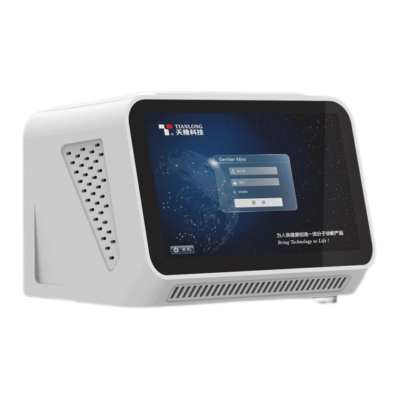
- Page 1 Real-Time PCR System Real-time PCR System User Manual Xi’an Tianlong Science and Technology Co., LTD. Bring Technology to Life...
- Page 2 Real-Time PCR System Disclaimer and Copyright Copyright © 2019 Xi’an Tianlong Science and Technology Co., Ltd. (hereinafter referred to as XATL Co., Ltd.). All rights reserved. All contents of this manual (including but not limited to text, trademark, logo, buttons icons, graphics, tables, data, etc.) are subject to the copyright and other intellectual...
- Page 3 Xi’an Tianlong Science and Technology corporate limited. Intended Use The Gentier mini real-time PCR system (hereinafter referred to as Gentier mini instrument) is intended for performing rapid, accurate polymerase chain reaction (PCR), meanwhile real-time measuring nucleic acid signals from DNA-binding fluorescent dyes or labeled probes and converts them to comparative quantitative readouts of DNA or reverse transcribed RNA.
- Page 4 Real-Time PCR System Safety Labels on Transport Package Label Description Fragile: The items inside are fragile, please handle with care. This Side Up: indicates the upward side of the transport package. Keep Dry: keep the transport package away from rain or any liquid.
- Page 5 Real-Time PCR System Moving Part: indicates that a certain moving part of Gentier mini instrument may cause personal injury. Reminding users to proceed with appropriate caution. IVD Equipment: Gentier mini instrument belongs to In Vitro Diagnostic equipment. Symbols Used in This Manual...
- Page 6 Real-Time PCR System Bold Refers to the instructions/options of the instrument system software. < Bold > Refers to the keys/icons of the instrument system software. Refers to the keys on computer keyboard. italic + Blue Indicates the reference chapter.
- Page 7 Real-Time PCR System Safety and Regulatory Compliance The operation, maintenance and repair of Gentier mini instrument shall strictly follow the safety specifications listed in this section and through this manual. The design of Gentier mini instrument has fully considered its biological contamination protection, electrical safety protection and mechanical motion protection.
- Page 8 Real-Time PCR System Prohibit: Never handling or move the instrument while it is running. Caution: For protection against overheating hazards, the openings on the instrument are designed for ventilation. Please do not block these openings or cover Gentier Mini instrument with dust cover and other materials while it is running.
- Page 9 Real-Time PCR System III. Electrical Safeties and Precautions Prohibit: Please cut off the power supply before opening the instrument shell, and it is prohibited to replace any part of the instrument while it is electrified. Caution: The instrument should be properly grounded. Any damage of the internal or external grounding path may cause danger.
- Page 10 Real-Time PCR System Prohibit: Spraying liquid on electrical parts may cause a short circuit and result in fire, so do not use sprays in vicinity of the instrument. Reminding: The working environment temperature of the instrument should be between 15° C~30° C, and the relative humidity should be between 20%~85%.
-
Page 11: Table Of Contents
Real-Time PCR System Contents A. OVERVIEW ............................. 1 A-1. A ..........................1 PPLICATION IELDS A-2. P ..............2 RODUCT ONSTITUTE AND NSTRUMENT TRUCTURE A-3. P ......................... 2 RODUCT NTRODUCTION A-3.1 Instrument Parameters and Characters ................2 A-3.1.4 Running Mode Difference ...................... 6 A-3.2 Software Characters ........................ - Page 12 Real-Time PCR System D. GENERAL MODE - INSTRUMENT SOFTWARE OPERATION ........19 D-1. S & M ..................19 TARTUP NTERFACE NTERFACE D-2. N ..........................22 XPERIMENT D-2.1 Experiment Settings ......................... 22 D-2.2 Run Monitoring .......................... 26 D-3. G ..........................28...
- Page 13 Real-Time PCR System F. ADVANCED MODE - INSTRUMENT SOFTWARE OPERATION ........114 F-1. M ..........................114 NTERFACE F-2. I ................... 116 NSTRUMENT OFTWARE PERATION F-2.1 Experiment File ........................117 F-2.2 Run Setting ..........................120 F-2.3 Run Monitoring ........................128 F-2.4 Result Analysis .......................... 132 F-2.5 General Setting .........................
-
Page 15: Overview
A. Overview A-1. Application Fields Gentier mini real-time PCR system is intended for performing rapid and accurate polymerase chain reaction (PCR). It can be used to detect target nucleic acids in biological samples, including nucleic acids of various pathogens (viruses, bacteria, mycoplasma, chlamydia, etc.) and genes. -
Page 16: A-2. Product Constitute And Instrument Structure
Real-Time PCR System A-2. Product Constitute and Instrument Structure Gentier mini real-time PCR system is mainly consisted of control system, power system, temperature control system, detection system, man-machine interface system and software (Version: V1), etc. A-3. Product Introduction A-3.1 Instrument Parameters and Characters A-3.1.1 Instrument General Parameters... - Page 17 Real-Time PCR System Application Environment: ► Temperature: 15° C ~30° C; Relative humidity: 20%~85%, non-condensing; Atmospheric pressure: 50.0kPa~106.0 kPa; Altitude: below 4000m; Storage and Transportation Environment: ► Temperature: -20° C ~55° C, with transport package; Relative humidity: 0%~ 93%; Running Noise: ►...
- Page 18 Real-Time PCR System A-3.1.2.3 Detecting Parameters Throughputs: simultaneously detect 16 samples; ► Repeatability: CV ≤ 0.5%; ► Linear Correlation:│r│≥ 0.990, within linear range of test items. ► A-3.1.2.4 Man-machine Interactive System Parameters Touch Screen: with built-in 7.0’ inches full-color touch screen. Gentier Mini ►...
- Page 19 Real-Time PCR System Operating System: applicable to Windows 7 64bit/32bit, Windows 8 ► 64bit/32bit and Windows 10 64bit/32bit. Application: Excel 2007(or higher configurations) ► Network Control: One computer can be connected with multiple Gentier mini ► instruments to realize the network centralized control and remote control.
-
Page 20: A-3.1.4 Running Mode Difference
Real-Time PCR System A-3.1.4 Running Mode Difference Function Description General Advanced Remarks Mode Mode √ √ Instrument Program Selection Ⅹ √ Instrument Program Editing √ √ Instrument Sample Application Ⅹ √ Detailed Sample Editing In General mode, users can set... -
Page 21: A-3.2 Software Characters
Real-Time PCR System A-3.2 Software Characters Software Interface: easy for operation, wizard-style interface, intuitive layout ► and program setting. Software Language: switchable multiple languages. Default languages are ► Chinese and English. Multiple Functions: multiple analyzing functions that adapt to various ►... -
Page 22: A-3.4 Consumable Specifications
Real-Time PCR System A-3.4 Consumable Specifications 0.2ml single PCR tube ► 0.2 ml 8-strip PCR tube ►... -
Page 23: Instrument Unpacking And Installation
Real-Time PCR System B. Instrument Unpacking and Installation B-1. Unpacking Instructions The transport package is as shown in figure B-1. Gentier Mini instrument and its accessories are well preserved in a carton case. In order to prevent the collision and oscillation during transportation, Gentier Mini instrument is sealed with dust cover and well supported by protective foams. -
Page 24: B-1.1 Unpacking Steps
Real-Time PCR System B-1.1 Unpacking Steps The unpacking of the transport package mainly includes 4 steps, as shown in figure B-2. The specific operations are as follows. Step 1: Cut off the packing belt and unseal the transport package. Step 2: Take out the instrument accessories and remove the protective foam on top of the instrument. -
Page 25: B-2. Working Environmental Requirements
Real-Time PCR System Reminding: In order to prevent the generation of condensed water, please do not open the transport package until it reaches the room temperature. Reminding: Please check the package integrity before open it. In case there is any damage, collision or water mark, please contact the transport department or our company. -
Page 26: B-2.2 Instrument Power Requirements
Real-Time PCR System While Gentier Mini instrument is running, the distance between the front and rear air vents and the nearest objects should not be less than 20cm; the distance between left and right air vents and the nearest objects should not less than 10cm. -
Page 27: B-3. Instrument Installation
Real-Time PCR System Prohibit: Spraying liquid on electrical parts may cause a short circuit and result in fire. Do not use sprays in vicinity of the instrument. Reminding: Under normal circumstances, please use the instrument attached power cord and adapter. If the original power adapter is destroyed, please substitute it with special accessories. -
Page 28: B-3.2 Application Software Installation
Real-Time PCR System Reminding: In advanced mode, program editing, experiment running and real-time monitoring can be operated offline. Reminding: Before setting up the network, please confirm that the main control computer is connected with external equipment such as monitor, keyboard, mouse, printer, etc., and then complete the installation of application software according to... -
Page 29: B-3.3 Computer Network Setting
Real-Time PCR System B-3.3 Computer Network Setting The network address of the main control computer should be set according to the default network information of the instrument to ensure that the main control computer can connect the identifiable instruments within LAN. - Page 30 Real-Time PCR System Figure B-3b. Main Control Computer Network Setting Step 3: Set Internet Protocol Version 4 (TCP/IPv4) on the control computer based on the following requirements: IP address: The first 3 octets of IP address on the main control computer should ...
-
Page 31: Preparation Before Experiment
Real-Time PCR System C. Preparation Before Experiment C-1. Instrument Self-inspection The instrument possesses self-inspection function. It will automatically carry out self- inspection after starting up. Users shall not perform any other operations at this stage to ensure that Gentier Mini instrument can work normally during the experiment. - Page 32 Real-Time PCR System Step 2: Press the release button to open the top lid, and load the PCR consumables with PCR system to be tested in the sample block. Step 3: Close the top lid until the lock catch makes a “click” sound.
-
Page 33: General Mode - Instrument Software Operation
Real-Time PCR System D. General Mode - Instrument Software Operation In general mode, the instrument can run independently without connection to the main control computer and output the experiment result. This chapter introduces the instrument software interfaces and basic operations in general mode. - Page 34 Real-Time PCR System The main interface consists of three parts: Status Bar, Menu Bar and a shortcut key New Experiment. 1. Status Bar: displays the current instrument status, and the system date and time. < WiFi >: indicates that the instrument has been connected to WiFi. The icon ►...
- Page 35 Real-Time PCR System Figure D-1.1. Main Interface – Menu Bar The hidden menu bar consists of three function tabs: < General Settings >, < Experiment Data > and < Shutdown/ Reboot >. < General Settings >: Press icon, and the software will enter the interface ►...
-
Page 36: D-2. New Experiment
Real-Time PCR System D-2. New Experiment D-2.1 Experiment Settings Users can edit and run the experiment program in the Experiment Settings interface. The interface consists of five parts: Title Bar, Experiment Name input box, Sample Setting area, Experiment Projects area and Run tab, as shown in figure D-2. - Page 37 Real-Time PCR System Figure D-2.1 Run Setting Interface – Keyboard Reminding: The system software defaults to name the current new experiment with the experiment creation time. Reminding: The experiment name can be included numbers, letters, horizontal lines, underlines, or Chinese characters, but cannot contain special characters.
- Page 38 Real-Time PCR System 4. Experiment Projects: displays experiment projects imported into the instrument. 8 common experiment projects can be listed in this area, and the experiment project can be selected by tapping the corresponding dialog box. < View More Projects >: Press View More Projects and all experiment projects will ►...
- Page 39 Real-Time PCR System Figure D-2.2. Experiment Setting Interface – Example of Experiment Setting The experiment name of the example is: exp-20210514125637 and there are 12 samples to be tested. 4 samples in the Group 1 (A1-A4); the selected experiment project is Test 1.
-
Page 40: D-2.2 Run Monitoring
Real-Time PCR System D-2.2 Run Monitoring After running the experiment, the system software will jump to the Run Monitoring interface, as shown in figure D-3. Users can real-time view the experiment running and detecting progress. D-2.2.1 Introduction of Run Monitoring Interface Figure D-3. - Page 41 Real-Time PCR System < Stop >: Users can press it to stop the running experiment. After the ► █ experiment stops, the instrument will send out 3 beeps and call up a dialog box, as shown in figure D-3.1. Click < OK > in the dialog box to confirm the status, and the software will return to the Startup Interface.
-
Page 42: D-3. General Settings
Real-Time PCR System Reminding: The software displays all tested samples and fluorescence curves of all channels by default. Figure D-3.2. General Mode – Run Monitoring – Details D-3. General Settings General settings interface includes two parts: Menu Bar and Information Display Area, as shown in figure D-4. -
Page 43: D-3.1 Settings Tab
Real-Time PCR System Figure D-4. General Setting Interface D-3.1 Settings Tab Settings tab includes four sub-tabs: Time, Brightness, Touch-tone and Language. The interface defaults to fold information for each sub-tab. Users can view details by clicking icon on the right of each sub-tab. -
Page 44: D-3.2 Network Tab
Real-Time PCR System Figure D-4.1 Basic Settings – Time D-3.2 Network Tab Network tab includes two sub-tabs: Network and WiFi. The interface defaults to fold information for each sub-tab, as shown in figure D-5. Users can view details by clicking icon on the right of each sub-tab. - Page 45 Real-Time PCR System Wired Network: displays the Physical Address and IP Address of the instrument, as shown in figure D-5.1. Physical Address cannot be edited and the IP Address can be set and edited, as shown in figure D-5.2. < Edit >: Users can touch the < Edit > button on the right of the IP Address to call ►...
-
Page 46: D-3.3 Projects Tab
Real-Time PCR System WiFi: Users can touch the cursor on the right of WiFi option to turn on or turn off the WiFi. When WiFi is open, the software interface will display WIFI which can be connected with the instrument. Users can touch the target WiFi and input the password to complete the connection. - Page 47 Real-Time PCR System < No. >: sequence number of the experiment projects. It is generated automatically ► when projects are imported in the instrument. < Abbr >: Users can set a short name for the experiment project when editing the ►...
-
Page 48: D-3.4 About Tab
Real-Time PCR System < Exit >: Users can press it to exit the Import/Export dialog box. ► < Local Project >: displays the local experiment project list. Users can select the ► check box to √ status in front of the target projects, then click <... - Page 49 Real-Time PCR System Instrument Information: displays Instrument Name, Instrument Model and Instrument Serial Number, as shown in figure D-7.1. The instrument name is editable. Users can press < Edit > button to call up the software keyboard, then input the new name and click < OK > to save it.
-
Page 50: D-4. Experimental Data
Real-Time PCR System D-4. Experimental Data Users can press the < Experimental Data > tab in the main interface to enter the Experiment Data interface, which stores the historical experiment information of the instrument. Users can view, analyze and print the data analysis results and real-time fluorescence curves of the historical experiments. -
Page 51: D-4.2 Result Analysis
Real-Time PCR System Experiment Information List: displays historical experiment information saved in the instrument or within the query period. Information of 12 experiments can be shown in a single page. Users can swipe the screen up and down to view more. - Page 52 Real-Time PCR System < Reanalyze >: reanalyze the experiment data after changing the parameter ► settings. Please refer to D-4.2.1 Result Analysis –Table Format Display for more details on the setting change. < Print >: After selecting the target sample number, users can click < Print > to ►...
- Page 53 Real-Time PCR System D-4.2.1 Result Analysis – Table Format The interface defaults to display the experiment information in the Table Format, as shown in figure D-9.1. The list shows information on Well Number, Sample Type, Sample Number, Experiment Project, Ct Value and Test Result of two channels.
- Page 54 Real-Time PCR System < Result >: Test results can be obtained based on the result criterion rule and Ct ► value analysis. Reminding: The result criterion rule is set by the technicians when they edit the experiment project templates and cannot be changed. If users need to change the rules, please create a new project on the external device and import the instrument.
- Page 55 Real-Time PCR System Reminding: The system software defaults to display real-time fluorescence curves and threshold lines of all channels of all samples. Real-time PCR Fluorescence: displays the real-time fluorescence curves and threshold lines (dotted lines parallel to X-axis) of the experiment results.
-
Page 56: Advanced Mode - Application Software Operation
Real-Time PCR System E. Advanced Mode - Application Software Operation This chapter introduces functions of the application software in advanced mode. The functions include user account management, new experiment creation, real-time monitoring and experiment data analysis, etc. E-1. Start Application Software... -
Page 57: E-2. Quick Start Bar
Real-Time PCR System Figure E-1.2 Startup Interface of Application Software The startup interface of application software is divided into two parts: Quick Start Bar and Main Interface. Quick Start Bar: collects commonly used functions for quick operations. Main Interface: As the core function area, Main Interface consists of Menu Bar, Tool Bar, Operation Area and Instrument Information Area. -
Page 58: E-2.1 User Management
Real-Time PCR System Figure E-2.1 Quick Start Bar E-2.1 User Management The current User Name is displayed on the top of quick start bar and users can click < Switch User > to change the current user account. Login: Users can click < Switch User > and input the registered account name in the input box;... -
Page 59: E-2.2 Quick Start
Real-Time PCR System Figure E-2.1b Quick Start Bar - Add User E-2.2 Quick Start Quick Start tab: includes five shortcut keys: < New Experiment >, < New Experiment from Test Template >, < New Experiment from Existing Experiment >, < Open Data File >... - Page 60 Real-Time PCR System Reminding: The application software defaults to name the current new experiment with the login user account name and experiment creation time. Reminding: The experiment name consists of numbers, letters, horizontal lines, underlines, or Chinese characters, but cannot contain special characters.
-
Page 61: E-2.3 Recent Files
Real-Time PCR System Reminding: When users select an experiment, the software will automatically judge and identify experiments that can run at the same time. After users select an experiment, the incompatible experiment options will disappear from the interface to avoid users’ selection errors. -
Page 62: E-2.4 Other Functions Of Quick Start
Real-Time PCR System Figure E-2.3 Quick Start Bar – Recent files E-2.4 Other Functions of Quick Start 1. Details: The details of the default instrument are displayed at the bottom part of quick start bar, including IP Address, On-line, Top Lid and Status. When users... -
Page 63: E-3. Main Interface
Real-Time PCR System E-3. Main Interface After closing the quick start bar, the application software will enter the main interface, which consists of menu bar, tool bar and operation area, as shown in figure E-3. Figure E-3. Main Interface E-3.1 Menu Bar The menu bar of application software includes five submenus: File (F), View (V), Tool (T), Option (O) and Help (H). - Page 64 Real-Time PCR System E-3.1.1 File(F) Submenu Options and Functional Description New Experiment (N): create a new experiment. For detailed functions, please refer to E-2.2 Quick Start - New Experiment. New Experiment from Test Template: Users can select a saved test template and create a new experiment file with the same experiment settings as the selected test template.
- Page 65 Real-Time PCR System 11. Export All Data Sheets to Excel ...: Users can choose a path to export the experiment data as an Excel file. 12. Report Management: After completing the experiment, users can edit and manage the report information of the current experiment.
- Page 66 Real-Time PCR System Status: displays the state of the connected instrument, which is Ready or Running; E-3.1.3 Tool(T) Submenu Options and Functional Description 1. Instrument Management: Click Instrument Management option in Tool submenu and the application software will call up the instrument management interface, which consists of three parts: Instrument List, Details tab and File Transmission, as shown in figure E-3.2.
- Page 67 Real-Time PCR System ► Instrument List: displays relevant information of connected instrument, including Model, Name, Serial No., Remarks, IP Address and whether the instrument is set as the Default Instrument. There are four function keys under the list: < Add >, <...
- Page 68 Real-Time PCR System Figure E-3.2b Instrument Management Interface - Edit Instrument Window Click < Delete > to delete the instrument selected in the list. Select any instrument in the Instrument List and click < Set as Default Instrument > to set it as the default instrument to connect with the application software.
- Page 69 Real-Time PCR System Computer Information Area: displays the IP address list of the Connected Computer within LAN. Running Information Area: displays the real-time Status of connected instrument, such as Stage, Cycle, Step and Remaining Time. a. Function Keys: ...
- Page 70 Real-Time PCR System Click to download the selected Local File to the connected instrument. Click to upload the selected Instrument File to the main control computer and save it in the Local Directory selected by users. 2. T...
- Page 71 Real-Time PCR System 3. Research Report: Click Research Report option in Tool submenu and the application software will pop up the research report interface, as shown in figure E-3.4. Reminding: Users can enter the scientific research report interface in conditions that they open a completed experiment and enter the analysis interface.
- Page 72 Real-Time PCR System ► Save Research Report: After editing the research report, please click < Save > icon to choose a path for saving the research report. Reminding: A research report can be saved as a PDF or html file.
- Page 73 Real-Time PCR System ► Function Keys: < Open Template > to open the local template. < Save Template > to save the new template. < Save Template as File > to save the template as a file. ...
- Page 74 Real-Time PCR System will be displayed in the list, which consists of five columns: No., Well, Dye, Internal Control and Gene. Users can check any check box in the Internal Control column to set it as the internal control of the current sample and edit the name of the target gene for any well in the Gene column.
- Page 75 Real-Time PCR System a. Analysis Options: Users can set Analytical Method, Select Stage and Select Step. Analytical Method: Users can select the corresponding analytical method for the current template in the Analytical Method drop-down box. Abs Quant and Melting Curve can be selected according to the corresponding operation programs.
- Page 76 Real-Time PCR System Parameter Name Remarks Manual Baseline Users can click the Manual Baseline check box to confirm whether to use this setting. Manual Baseline is selected by default. Manual Threshold Users can click the Manual Threshold check box to confirm whether to use this setting.
- Page 77 Real-Time PCR System Negative Ct Threshold After selecting a single well in the parameter list, select “>”, “≥” or “No Ct”, then click keys or input Ct Value manually to set the CT threshold rule to judge the test result as negative.
- Page 78 Real-Time PCR System Figure E-3.6 Tool Submenu - Test Template Management Test Template List: Users can view the test template information saved by the ► current application in the test template list, including Test ID, Test Name, Suitable Instrument Model(s), Create Time and Modify Time.
- Page 79 Real-Time PCR System E-3.1.4 Option(V) Submenu Options and Functional Description Configuration Management: consists of three function tabs: Default Path, Standard Temperature Template and PANA. Click Configuration Management option in the Option submenu and the application software will pop up the configuration management interface, as shown in figure E-3.7a.
- Page 80 Real-Time PCR System Do You Want to Use The Last Saved Position: Users can check Do you want to use the last saved position check box to determine whether to use the same default file path for saving experiment file or template next time.
- Page 81 Real-Time PCR System Figure E-3.7c Configuration Management Interface - PANA Tab a. Users can check the check box of Connect to PANA and enter the IP address of the PANA automatic nucleic acid workstation to be connected in the IP Address box.
- Page 82 Real-Time PCR System User: Click User in the Option submenu and the application software will pop up the user interface, which consists of two tabs: User Management and General User Permissions. Admin Mode: When logging into the software with admin user account (the ►...
- Page 83 Options and Functional Description User Manual: opens Gentier mini Real- time PCR System User Manual. Home Page: visits the home page of Xi’an Tianlong Science and Technology Co., Ltd. About: displays the application software version and copyright information, as shown in figure E-4.
-
Page 84: E-3.2 Tool Bar
Real-Time PCR System E-3.2 Tool Bar The Tool Bar of the application software consists of nine commonly used function icons and eight additional function icons displaying on the different interfaces. 1. Nine Commonly Used Function Icons < New Experiment >: create a new empty experiment. - Page 85 Real-Time PCR System < Choose Run Parameter Template >: Click this icon in the tool bar and the application software will pop up Choose Run Parameter Template window. Users can choose a saved run parameter template to set the current experiment based on the selected template.
-
Page 86: E-3.3 Operation Area
Real-Time PCR System < Export Lis >: Users can click this icon in the tool bar to export the current experiment data. One export file format (csv) is provided in English mode. E-3.3 Operation Area After creating a new experiment file or open an experiment file, the operation area on the main interface of the application software will be activated, as shown in figure E-5. - Page 87 Real-Time PCR System Four tabs: Run Setting, Sample Setting, Run Monitoring and Analysis are added in the operation area. Users can select corresponding tabs for experiment setting and monitoring. Reminding: Analysis interface is activated only when users open a completed experiment.
- Page 88 Real-Time PCR System Run Setting The Run Setting interface consists of five parts: temperature program area, stage and step lists, experiment and step setting areas. Temperature Program Area: Users can view the temperature program of the current experiment, or edit the temperature program stages and steps in this area, as shown in figure E-6.1.
- Page 89 Real-Time PCR System Step: Each step is an independent temperature control progress. ► Each step is separated by thin and solid light blue lines. The step number is shown in the middle of the box above each step. Click <...
- Page 90 Real-Time PCR System Figure E-6.2 Experiment Editing Area Reaction Volume: Users can enter the reaction volume for current experiment in ► the Reaction Volume input box. Reminding: The reaction volume setting range is 0μL - 100μL. Lid Heating: Users can enter the hot lid temperature for current experiment in the ►...
- Page 91 Real-Time PCR System Cycle: displays the cycle number of each stage. Users can double click this number, then manually enter or use keys to set the cycle number of the selected stage. Reminding: Users can also double click the cycle number below the stage box in the temperature program area to complete the cycle setting.
- Page 92 Real-Time PCR System Figure E-6.4 Stage Type Window The application software provides the following stage types: Preincubation, ► Reverse Transcription, 2 Step Amplification, 3 Step Amplification, Melting, Continuous Melting and Cooling. Users can choose the corresponding predefined stage in the stage type window and click < Add > to add the selected stage; or double click any stage to add directly.
- Page 93 Real-Time PCR System Step List: as shown in figure E-6.5. Figure E-6.5 Step List Step List: displays step information of the selected stage. ► Step: displays the number of each step. Temperature: displays the target temperature of the current step.
- Page 94 Real-Time PCR System Step Setting: Users can edit the parameters of the selected step in the step setting dialog box or step setting area. According to the different step modes of the experiment, the parameters to be edited are also different.
- Page 95 Real-Time PCR System Touchdown Step Mode: the touchdown step mode allows the temperature program to change the annealing step temperature from the initial temperature to the target temperature as the cycling proceeds. Users can set the corresponding parameters in the Step Setting dialog box, as shown in figure E-6.6b.
- Page 96 Real-Time PCR System Figure E-6.6c Step Setting Dialog Box – Long Step Mode Reminding: The initial and target time setting range is 1s~60min. Reminding: the delta time setting range is 1s~10min. Reminding: The start cycle range is 1~Max cycle number of the current stage.
- Page 97 Real-Time PCR System Reminding: Fluorescence is read in the last step of the melting stage by default, so users do not need to set it. Reminding: The temperature increment setting range is 0.1° C - 5.0° C. Continuous Melting: Continuous melting stage allows the system to read the fluorescence more frequently.
- Page 98 Real-Time PCR System Figure E-7. Sample Setting Interface Sample Setting Operation Sample Setting Area: After entering the sample setting interface, users shall first choose a sample well in the sample setting area, as shown in figure E-7.1. The well distribution in sample setting area corresponds to the well distribution of the sample block in loading platform.
- Page 99 Real-Time PCR System Figure E-7.1 Sample Setting Interface - Sample Setting Area Introduction to Sample Setting Area ► User can select relevant sample wells in the sample setting area and operations are as follows: Click and select a single well in sample setting area.
- Page 100 Real-Time PCR System Click < All > on the top left corner of sample setting area to select all sample wells. Sample Property Setting Area: After selecting one or more sample wells in the sample setting area, users can set the properties for the corresponding wells in the sample property setting area.
- Page 101 Real-Time PCR System Reminding: The sample type and the well identification color are consistent with the sample type keys below the well setting area. Sample: Users can enter sample name of the selected well in the Sample Type input box, or select the previously entered sample name from the drop-down menu.
- Page 102 Real-Time PCR System Standard Conc.: Users can select a single standard sample and enter its standard concentration in Standard Conc. input box. Conc Unit: Users can select a single standard sample and set its concentration unit from Conc Unit drop-down list; the application software provides two default concentration units: IU/ml and Copies/ml.
- Page 103 Real-Time PCR System Users can set the starting concentration for a series of diluted standard samples in the Starting Conc. input box. Users can select the concentration dilution factor for a series of diluted standard samples from Dilution Factor drop-down list.
- Page 104 Real-Time PCR System a. Replicate No.: Users can select the corresponding sample wells in the sample setting area and select the replicate group number from the Replicate No. drop- down list, to classify the selected same samples into one replicate group.
- Page 105 Real-Time PCR System User can select the direction for auto setting from Direction drop-down list: Horizontal (from Left to right) and Vertical (from up to down). Click < OK > and the application software will automatically divide the replicate group for all the selected samples.
- Page 106 Real-Time PCR System Reminding: The Sample ID setting is primarily intended to facilitate operators to identify and differentiate samples. Samples can only be identified and confirmed according to the Unique ID. QC Failure Condition Setting: After completing the sample well setting, please ►...
- Page 107 Real-Time PCR System E-3.3.3 Run Monitoring After finishing the experiment run setting and sample setting, users can click Run Monitoring tab to enter the run monitoring interface to run the experiment and monitor the experiment running process, as shown in figure E-8.
- Page 108 Real-Time PCR System Full-screen display of function modules: Users can click the < Full Screen > icon on the top right corner of each area to display the current functional module of the area in full screen. Run & Stop experiment: Users can click < Run > key in the Run Info functional ...
- Page 109 Real-Time PCR System Figure Run Monitoring Interface Coordinate Range Setting E-8.1a. Automatic Adjustment: If the Automatic option is selected, the application software will automatically adjust the Y-axis coordinate according to the detected fluorescence value. Manual Adjustment: If the Manual option is selected, users can manually enter ...
- Page 110 Real-Time PCR System < Display Mode > : Users can set fluorescence curve display ► mode from the drop-down list on the bottom left of Real-time Fluorescence functional module. The real-time fluorescence curve can be displayed according to Dye Color and Well Color. The interface displays Dye Color by default.
- Page 111 Real-Time PCR System Function key introduction: Users can click < Export > icon to export the ► temperature program monitoring diagram of the current experiment. Sample Setting: displays the sample well setting of the current running experiment, as shown in figure E-8.3.
- Page 112 Real-Time PCR System Figure E-8.4 Run Monitoring Interface - Run Info Function Module Instrument List: The information of connected and running instrumentS are ► listed. Function Key Introduction: ► User can click < Run > key to run the current experiment.
- Page 113 Real-Time PCR System Heat Map: displays the real-time fluorescence heat map of the current running experiment, as shown in figure E-8.6. Figure E-8.6. Run Monitoring Interface - Heat Map Function Module E-3.3.4 Analysis After experiment completed, users can click the Analysis tab to enter the analysis interface.
- Page 114 Real-Time PCR System Figure E-9. New Analysis Window Select Stage: User can choose the stages that need to be analyzed. Select Step: User can choose the step that need to be analyzed. Analysis Method: shows the current analysis method for the current step/stage.
- Page 115 Real-Time PCR System The relative quantification analysis interface consists of seven functional modules: Amplification Curve, Standard Curve, Sample Setting, Result Table, Raw Curve, Raw Fluorescence and Heat Map. The relative quantification analysis interface is divided into four areas. When users enter the analysis interface, the application software displays four functional modules (Amplification Curve, Standard Curve, Sample Setting, Result Table) by default, as shown in figure E-10.
- Page 116 Real-Time PCR System Interface Introduction and Parameter Description Amplification Curve: displays the diagram of fluorescence intensity RFU (Y-axis) against cycle number (X-axis) of the current experiment, as shown in figure E-10.1. The dotted line parallel to the X-axis is the threshold value of the amplification curve.
- Page 117 Real-Time PCR System Dye Color & Well Color: is the same as the description E-3.3.3 Run Monitoring - 1. Real-time Fluorescence. Sample Color & Gene Color: If users set the Sample and Gene in Sample Setting, the amplification curve can be displayed respectively in colors of Sample and Gene.
- Page 118 Real-Time PCR System Figure E-10.3 Abs Quant analysis interface - Standard Curve functional module Parameter Introduction: ► Dye: displays the relevant dye of standard curve. Target Gene: displays the target gene of standard curve. Slope: displays the slope of standard curve.
- Page 119 Real-Time PCR System Figure E-10.3a. Abs Quant Analysis Interface - Standard Curve Window Import Standard Curve: Users can click < Import > key and select a saved standard curve file, then import it to the standard curve list. The corresponding standard curve diagram will be displayed in the Standard Curve Preview area below.
- Page 120 Real-Time PCR System Standard Curve Preview: displays the preview of selected standard curve(s) to be loaded. < Clear Std Curve >: Users can click < Clear Std Curve > to clear the standard ► curves displayed on the Standard Curve functional module.
- Page 121 Real-Time PCR System Figure E-10.4a Result Table functional module – Result sub-tab User can double click the title of each column to sort all sample results according to the content in this column. User can click the title of each column and drag the column to the left or right to adjust the sequence of sample results.
- Page 122 Real-Time PCR System < Export >: Users can click this icon to save the current result data to a specified path. Figure E-10.4c Result Table functional module – Table management Raw Curve: displays the diagram of raw amplification curve without subtract baseline, as shown in figure E-10.5.
- Page 123 Real-Time PCR System Figure E-10.5 Abs Quant analysis interface - Raw Curve functional module VI. Raw Fluorescence: displays the raw fluorescence data map of the current experiment, as shown in figure E-10.6. Figure E-10.6 Abs Quant analysis interface - Raw Fluorescence functional module Function key introduction: ►...
- Page 124 Real-Time PCR System VII. Heat Map: displays the Ct, Concentration, Fluorescence heat map and QC diagram of the current experiment, as shown in figure E-10.7. Figure E-10.7 Abs Quant analysis interface – Heat Map functional module Ct: Users can check Ct option and click any dye to view the relevant Ct heat map.
- Page 125 Real-Time PCR System Amplification Plot tab: Users can set the Analysis Mode and Analysis Method of the current experiment in the Amplification Plot interface, as shown in figure E- 11.1. Figure E-11.1 Abs Quant Analysis Setting interface - Amplification Plot tab Analysis Mode: consists of 4 modes: Baseline Gain Calibration, Reverse Curve, ►...
- Page 126 Real-Time PCR System Hypersensitive: For amplification experiments with high sensitivity requirements, users can check the Hypersensitive analysis mode for experiment data analysis. Baseline: When users select Baseline Gain Calibration and Hypersensitive ► analysis mode, the application software provides two baseline setting methods: Automatic Baseline and Manual Baseline.
- Page 127 Real-Time PCR System Figure E-11.2 Abs Quant Analysis Setting interface – Gene and Sample tab Dye and Gene: displays the name of target gene and its marking dye. ► User can check a certain check box in the Remove column and click < OK > to ...
-
Page 128: Advanced Mode - Instrument Software Operation
Real-Time PCR System F. Advanced Mode - Instrument Software Operation This chapter introduces the functions of Gentier Mini instrument software: Experiment File, Run Setting, Run Monitoring, Result Analysis and General Setting. F-1. Main Interface After the instrument switched on and automatically conducting self-inspection, the touch screen will display the main interface of advanced mode, which is consisted of status bar, operation area and main function keys, as shown in figure F-1. - Page 129 Real-Time PCR System System Status: displays the current instrument system status in the form of text on ► the left of the status bar. Initializing: The instrument system is in the process of initialization. Ready: The instrument system initialization is completed and ready for running.
-
Page 130: F-2. Instrument Software Operation Area
Real-Time PCR System < Pause Experiment >: Pause the current running experiment. This function ► key is activated when the experiment is Running. < Stop Experiment >: Stop the current running experiment. This function key ► is activated when the instrument system is under Running or Pause status. -
Page 131: F-2.1 Experiment File
Real-Time PCR System F-2.1 Experiment File The main interface of instrument software displays the experiment file tab by default. This tab is consisted of three parts: experiment file display area, experiment file information area and experiment file operation bar, as shown in figure F-2.1a. - Page 132 Real-Time PCR System Users can press the icon on the top left corner of the experiment file display ► area and it will turn into icon, and the display mode of the experiment file display area will change from icons to file details list, as shown in figure F-2.1b.
- Page 133 Real-Time PCR System Reminding: The system will pop up a keyboard to name the new experiment file, as shown in figure F-2.1c. User can press < Close > to exit the keyboard. Reminding: the instrument software will name the new experiment file with creation date and time by default.
-
Page 134: F-2.2 Run Setting
Real-Time PCR System F-2.2 Run Setting The run setting tab consists of two sub-tabs: Temperature Setting and Fluorescence Setting. Users can set temperature, cycle, reaction volume, lid heating and fluorescence of a new experiment, or view and edit the experimental settings of a selected experiment. - Page 135 Real-Time PCR System Temperature Setting sub-tab consists of four function areas: Reaction Volume, Lid Heating, Stage Setting Box and Step Setting Box. Reminding: Users need to create stages and steps for a new experiment by pressing function keys. Reaction Volume: User can manually input numbers or press icons to set the reaction volume.
- Page 136 Real-Time PCR System Function Keys: consists of four function keys. See F-2.2.1.2 Temperature Setting ► Steps for more details. < Up >: Move up the selected step. < Add >: Add a new step. < Delete >: Delete the selected step.
- Page 137 Real-Time PCR System Seven predefined stage types are provided by the instrument software for users: ► Preincubation, Reverse Transcription, 2 Step Amplification, 3 Step Amplification, Melting, Continuous Melting and Cooling. User can also press Custom Stage to define the stage setting according to specific experiment requirements.
- Page 138 Real-Time PCR System Reminding: Users can set only one fluorescence reading step in one stage. Step 5: Edit step Users can select a certain step in the step setting box, and press the icon in the corresponding Edit column; the instrument software will pop up the step edit window, which consists of two areas: Step Mode and Temperature Parameters.
- Page 139 Real-Time PCR System The touchdown step mode allows the temperature program to change the annealing ► step temperature from the initial temperature to the target temperature as the cycling proceeds. User can press the input boxes of Initial Temp., Target Temp., Delta Temp. and ►...
- Page 140 Real-Time PCR System Figure F-2.2.e Step Edit window - Long step mode Step Setting of Melting Stage: Melting stage has three steps by default. The editing of the first two steps is the same as those of the standard step mode. If the current step is the last step of a melting stage, the step setting window is as shown in figure F-2.2.f.
- Page 141 Real-Time PCR System Step Setting of Continuous Melting Stage: Continuous melting stage has four steps by default. The editing of the first three steps is the same as those of the standard step mode. If the current step is the last step of a continuous melting stage, the step setting window is as shown in figure F-2.2.g.
-
Page 142: F-2.3 Run Monitoring
Real-Time PCR System Figure F-2.3. Run Setting Interface - Fluorescence Setting sub-tab User can check the corresponding check box in the Channel column to set the fluorescence channel for the current experiment. Users can press the corresponding icon in the Dye column and select the ... - Page 143 Real-Time PCR System Figure F-3. System software – Run Monitoring interface Run Status Bar: displays the real-time running status of the current experiment, including Remaining Time, Stage, Cycle and Step. Run Monitoring Option Bar: Users can select Fluorescence or Temperature option in the run monitoring option bar to monitor the corresponding content of the current experiment.
- Page 144 Real-Time PCR System Fluorescence: Users can press keys below the run monitoring ► diagram to choose the monitor content: real-time Amplification curve, Melting curve or fluorescence Heat Map of the current experiment. Amplification: The run monitoring diagram will display the real-time Amplification curve of the current experiment by default, as shown in figure F-3.1.
- Page 145 Real-Time PCR System Figure F-3.2 Run Monitoring Diagram - Real-time Melting Curve X axis represents the temperature. Y axis represents the Relative Fluorescence Unit (RFU). User can press any dye under the Fluorescence option in the run monitoring ...
-
Page 146: F-2.4 Result Analysis
Real-Time PCR System Figure F-3.3 Run Monitoring Diagram - Heat Map Fluorescence heat map displays the 16 sample wells corresponding to the sample block. The color bar on the right side of fluorescence heat map displays the change ... - Page 147 Real-Time PCR System Figure F-4.1 Run Monitoring Diagram - Fluorescence heat map Amplification Result: Users can press any well on the fluorescence heat map to ► check the amplification result of this sample, as shown in figure F-4.2. Figure F-4.2 Run Monitoring Diagram - Amplification result...
-
Page 148: F-2.5 General Setting
Real-Time PCR System The amplification result interface displays the Amplification Curve, Well and Ct value information. Use can click Previous Well to check the amplification result of the previous well sample. Use can click Next Well to check the amplification result of the next well sample. - Page 149 Real-Time PCR System Introduction to Instrument sub-tab Instrument Serial Number: displays the factory serial number (SN) of the ► current instrument. Instrument Model: displays the current instrument model. ► Instrument Name: displays the name of the current Gentier mini instrument.
- Page 150 Real-Time PCR System Figure F-5.2 General Setting tab - Configuration sub-tab Introduction to Configuration sub-tab Network Information: displays the network information of Gentier Mini ► instrument. Press < Edit > and the instrument software will pop up the network information window, as shown in figure F-5.2a.
- Page 151 Real-Time PCR System Figure F-5.2a Configuration sub-tab - Network Information window In the IP Setting box, user can view all the network IP addresses, or press < Edit > to modify the corresponding parameter. Default: Users can press < Default > to recover the default network IP settings of ...
- Page 152 Real-Time PCR System Figure F-5.2b Instrument sub-tab - Date/time setting window < > / < >: Users can press icons to set the displayed year. < > / < >: Users can press icons to set the displayed month.
- Page 153 Real-Time PCR System F-2.5.3 Service Sub-tab Users can view or edit the setting information of instrument system, as shown in figure F-5.3. Figure F-5.3 General Setting tab - Service sub-tab Introduction to Service sub-tab Clear Memory: press < Clear > to clear all experiment files.
-
Page 154: Instrument Cleaning And Maintenance
Real-Time PCR System G. Instrument Cleaning and Maintenance Under proper using conditions, Gentier Mini instrument requires little maintenance. However, Gentier Mini instrument should be cleaned and maintained on a regular schedule for long time and constant use. This section includes the information on cleaning and maintenance of Gentier Mini instrument. -
Page 155: G-1.2 Clean Touch Screen
Real-Time PCR System step: Clean the instrument shell with a piece of damp, soft cloth, and if needed, please rinse the cloth with mild commercial detergent for cleaning. Prohibit: Do not spray the detergent directly on the instrument, as malfunctions of the electronics or may occur. -
Page 156: G-2. Instrument Maintenance Operation Instructions
Real-Time PCR System step: Open the top lid and clean the sample block surface with a piece of damp, soft cloth, and if needed, please rinse the cloth with mild commercial detergent. step: Clean the sample block wells with the degreased cotton swab moistened with ethanol to ensure the firm contact and good thermal conductivity between the consumables and the wall of block well. -
Page 157: G-2.3 Maintain Instrument Cleanliness
Real-Time PCR System G-2.3 Maintain Instrument Cleanliness Contamination of sample block or optical parts can interfere with thermal cycling and data collection. Avoid contaminating the Gentier mini instrument: Always clean the outside surface of consumables before placing them in the ... -
Page 158: G-3.2 Product Packaging
Real-Time PCR System Prepare the detergent (lab routine disinfectant), wet the cotton cloth and degreased ► cotton swabs with the prepared detergent. Clean the sample block surface with the cotton cloth, clean the sample block well ► with the degreased cotton swabs, and leave the top lid open until it is dry. - Page 159 Real-Time PCR System Figure G-1. Exploded View of Package Caution: The original transport package of Gentier mini instrument is designed to reduce the instrument damage and ensure its transportation safety. Adopt other packaging materials will break the warranty, and XATL Co., LTD. will not be responsible for damages as consequences of improper packaging that incur during the transportation back to maintenance department.
-
Page 160: G-4. Troubleshooting
Real-Time PCR System G-4. Troubleshooting In general, corrective instructions will be displayed along with the error messages by the application or instrument software. And under normal circumstances the software running errors can be solved by restarting the computer or the instrument system. - Page 161 Real-Time PCR System Experiment settings do not meet the requirements (temperature is Reset the experiment procedure inappropriate or cycle number is not enough). Others Contact us Abnormal Air vent is blocked Clean up the air vent. ramp or incorrect Connecting lines are loose. Contact us...
-
Page 162: After-Sale Service Commitments
Real-Time PCR System H. After-sale Service Commitments H-1. Warranty Service In the condition that user comply with the rules of transportation and operation. Our company guarantees to exchange the Gentier mini instrument in case any malfunction is caused by the defects of materials and instrument manufacture within 1 month after sale. -
Page 163: H-2. Response Time
7 days for the customs located in China. H-3. Contact Information Company Name: Xi’an TianLong Science and Technology Co., LTD. Company Address: No. 389, Zhuhong Road, Xi’an, Shaanxi, China Postcode: 710018... -
Page 164: Appendix 1 - Product Accessories List
Real-Time PCR System Appendix 1 - Product Accessories List List Qty. Replacement Period Remark Power cord Replace after damage 1.5m Network cable Replace after damage 2.0m Power adapter Replace after damage ADT-150A24AA User manual Certification Packing list Warranty card...
Need help?
Do you have a question about the Real-time PCR System and is the answer not in the manual?
Questions and answers