Table of Contents
Advertisement
Quick Links
Advertisement
Table of Contents

Related Manuals for Tianlong GeneRotex 96


Summary of Contents for Tianlong GeneRotex 96
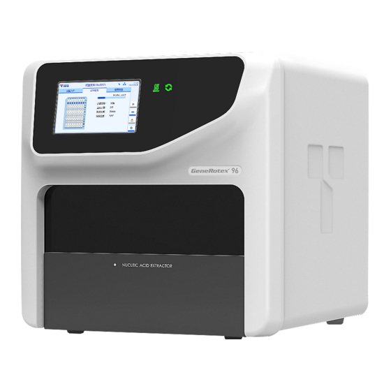
- Page 1 Full-Automatic Nucleic Acid Extraction System GeneRotex 96 Service Manual...
- Page 2 This manual and all its intellectual property rights (including copyright) are owned by Tianlong. Without the prior written permission of Tianlong, no one shall use, disclose or allow others by any means to obtain all or part of the information in this manual . Without the prior written permission of Tianlong, no one shall (but not limited to) photograph, copy, reproduce or translate into other languages all or part of contents of this manual.
- Page 3 The product needs to be repaired due to the following causes even in the warranty period: Man-made damage; grid voltage beyond the specific scope of the equipment; acts of god. Tianlong will not be responsible for the direct, indirect or final damage and delay arising from the following causes (including but not limited to): Improper use;...
-
Page 4: Table Of Contents
Contents Chapter 1 Safety and Precautions..........................5 1.1 General Safety and Precautions........................5 1.2 Personal Safety and Precautions........................6 1.3 Electrical Safety and Precautions........................6 1.4 Environmental Safety and Precautions......................7 1.5 Bio-safety and Precautions..........................8 Chapter 2 System Overview............................9 2.1 Applicable Scope............................9 2.2 Product Composition and Structure....................... -
Page 5: Chapter 1 Safety And Precautions
Xi'an Tianlong Technology Co., Ltd. shall not bear any responsibility for any loss caused by the user not reading this manual or failing to operate the instrument in accordance with the contents of this manual! Caution: Please read this manual carefully before using the instrument. -
Page 6: Personal Safety And Precautions
Caution: If this instrument needs to be installed or transported, please contact us to request professionals or professional guide. Otherwise, we shall not bear any responsibility for the damage caused to the instrument. Caution: After the instrument is installed, the transportation lock shall be properly kept in accordance with the technician’s requirements. -
Page 7: Environmental Safety And Precautions
Reminder: Generally, please use the power cord that comes with the instrument. If the original power cord is broken, worn or disconnected, replace it with an equivalent power cord as soon as possible. Caution: To avoid the risk of electric shock, the power cord of this instrument must be reliably grounded. The power cord of this instrument is a standard three-plug power cord. -
Page 8: Bio-Safety And Precautions
1.5 Bio-safety and Precautions Biohazard: The sample object of this instrument is nucleic acid. In actual operation, please treat it as a biological sample with potential biological hazards. During the sample handling and operation, generally applicable safety protection actions shall be taken, and appropriate protective goggles, clothing and gloves shall be worn. Biohazard: The user shall dispose of the discarded sample and contaminated materials in accordance with the relevant local or national applicable regulations. -
Page 9: Chapter 2 System Overview
Chapter 2 System Overview 2.1 Applicable Scope The full-automatic nucleic acid extraction system can be widely used in scientific research, clinical, disease control, food safety, forensic and other fields. Users only need to add samples and paramagnetic particle method nucleic acid extraction reagents, load reaction consumables, and the full-automatic nucleic acid extraction system will complete all nucleic acid extraction operations in accordance with the experimental procedures. - Page 10 Back Figure 2-2 Back of Full-automatic Nucleic Acid Extraction System Introduction to 1.Heat emission hole on the back 2.Three-in-one switch functions: 3.UV lamp door 4.USB interface...
-
Page 11: Conventional Parameters
4.Heating upper plate 5.Transportation lock 6.Rotary sleeve frame 7.UV lamp 8. Power wind shield 9.Tianlong 96 deep hole plate 2.0 (anti-static) 10.Deep hole plate positioning block 11.Push rod slide way 12. Horizontal pushing belt wheel cover plate 2.3 Conventional Parameters Product specification: 490mm(L)×510mm(W)×480mm(H) Weight: 45 Kg... -
Page 12: Chapter 3 Installation Requirements And Procedure
Chapter 3 Installation Requirements and Procedure 3.1 Installation Requirements 3.1.1 Environmental Requirements a) Only applicable to an indoor environment with good ventilation, no corrosive gas and no strong magnetic field interference b) Avoid using it in direct sunlight, keep it away from heaters, stoves and all other heat sources, and away from water sources, such as pools and water pipes. -
Page 13: Appearance And Configuration Inspection
instrument Use a conforming multimeter to measure the supply voltage and the voltage between the neutral wire and the ground wire After the measurement is completed, record the corresponding data in the Nucleic Acid Extraction System Installation and Acceptance Report 3.2.2 Appearance and Configuration Inspection Check whether the inner and outer packaging of the instrument is intact, whether it is damaged, bumped, soaked, affected by damp and deformed, etc. - Page 14 Figure 3-1. Exploded View of Packing Container Instrument unpacking procedure Step1: Please transfer the product packing container to the working place and open the sealing strip of the packing container, as shown in Figures a and b. Step 2: Open the top cover of the packing container and remove the rubber buckles on both sides of the packing container (4 pieces in total);...
- Page 15 Figure 3-2 Unpacking Procedure Reminder: To prevent the generation of condensed water, do not unpack the instrument before the container reaches the room temperature. Reminder: Before unpacking the instrument, please carefully check the integrity of the product packaging. If there are defects, collisions or water logging marks, please contact the Transportation Department or us to solve the specific matters.
-
Page 16: Instrument Installation
Selection of other packaging materials will invalidate the warranty. Xi'an Tianlong Technology Co., Ltd. will not be liable for any damage to the instrument due to improper packaging during transportation. Please also keep the instrument related documents provided by us for future use. -
Page 17: Performance Test
3.4.1 Reagents and Tools Preparation Reagents Preparation Before using the product, the user shall select the corresponding paramagnetic particle method nucleic acid extraction reagent. In this manual, the "Full-Automatic Nucleic Acid Extraction System GeneRotex 96 Installed Kit" of Tianlong Technology Co.,... -
Page 18: Test Items And Procedure
Ltd. is used as an example for description. 3.4.2 Test Items and Procedure Please refer to the “Instructions for Use of Full-Automatic Nucleic Acid Extraction System GeneRotex 96 Installed Kit” Loading of consumables Place the stirring sleeve correctly at columns 2 and 8 of 96-deep-hole plate. -
Page 19: Chapter 4 Troubleshooting
Chapter 4 Troubleshooting Disassembly: Remove 2 bolts on the back panel with the M3 hexagonal tool to remove the top shell, remove the 6 bolts on both sides of the back panel and 1 bolt below the left and right side panels to remove the left and right shells. -
Page 20: Lcd Abnormality (Screen Scratch, Screen Reversal And Contact Failure, Etc.)
Connection Description of Main Control Panel Terminals Magnetic motor interface Horizontal pushing DC input interface motor interface Photoelectric switch interface close to the horizontal pushing motor on the base plate Rotary motor interface Another photoelectric switch interface on the base plate Magnetic absorption, left UV power cord photoelectric switch... -
Page 21: Reset Failure And Position Overranging Of Horizontal Pushing Motor
circuit board will result in the above abnormalities). If all above items are normal, replace the display module. Maintenance Method: Unplug the network cable, 2 USB extension cables, and the power cord on the back of the screen, and then remove the 4 fixed screws on the back of the screen to remove the display module. - Page 22 the horizontal pushing motor and the motor synchronous pulley is loose. If all items above are normal, replace the main control panel. You need to enter the commissioning mode before replacing the main control panel to record all motor parameters. After the replacement, manually enter all parameters and check the alignment position of the instrument.
- Page 23 axial section of the motor. Install it on the rotating shaft of the 42 motor at the direction as shown in the figure, and then place it on the fixed height-limiting tooling of the synchronous belt pulley according to the method as shown in the figure. Tighten two jackscrews to fix the belt pulley P5 (the jackscrews need to be coated with 243 medium-strength thread glue.
-
Page 24: Reset Failure And Position Overranging Of Lifting Motor
4.3 Reset Failure and Position Overranging of Lifting Motor Fault description: The lifting motor is at the abnormal position and cannot run to the designated position. Troubleshooting: 1. Check whether the motor shading plate and lifting photoelectric switch can sense each other. Insert and extract the power cord of lifting motor and photoelectric switch wire of lifting motor again, restart the instrument (the shading plate must be lower than the photoelectric switch position before the instrument is restarted) to check whether the lifting motor runs (whether the rotating sleeve frame moves... - Page 25 2. If the motor does not run and the red indicator of the photoelectric switch is off, you need to replace with new materials, remove the back panel, replace the faulty components with new ones, and re-route the wires according to the original wiring position, as shown in the figure below. Lifting motor photoelectric Lifting motor (above the switch...
- Page 26 4. If steps 2 or 3 have been carried out, the loading position and magnetic absorption position of the stirring sleeve must be checked as follows: 1) Take at least 4 deep-hole plates, place them at positions 1, 3, 4, 6 of the experiment module and correctly place the stirring sleeve at columns 2 and 8;...
-
Page 27: Reset Failure And Position Overranging Of Magnetic Motor
Stirrin Magne Magnetic bar position sleeve line tic bar Make a confirmation, click “Save” and “Backup Parameter” (only for new version), restart the instrument and follow up the experiment results. 4.4 Reset Failure and Position Overranging of Magnetic Motor Fault Description: ... - Page 28 Maintenance Methods: If the shading plate and photoelectric switch cannot sense each other, re-adjust the position of the shading plate, place the shading plate at the central position of 2 corners of the photoelectric switch, and the distance between the shading plate and the photoelectric switch shall be appropriate (it can shield the photoelectric switch signal without contact).
-
Page 29: Module Door Motor Reset Failure
4.5 Module Door Motor Reset Failure Fault Description: The module door is at the abnormal position and cannot run to the designated position. Troubleshooting: When the instrument is powered off, slowly pull the module door with hand and repeat this action for 5-10 cycles. - Page 30 If the shading plate and photoelectric switch cannot sense each other, re-adjust the position of the shading plate, place the shading plate of the module door motor at the central position of 2 corners of the photoelectric switch, and the distance between the shading plate and the photoelectric switch shall be appropriate.
-
Page 31: Chapter 5 Maintenance
Chapter 5 Maintenance Fault Troubleshooting Solution 1: Check whether the power supply is normal Screen display failure after the Replace the faulty 2: Check whether the fuse is normal instrument is powered on parts 3: Check whether the switching power supply is normal 1: Check whether the UV lamp tube is normal Replace the faulty The UV lamp is not on... - Page 32 drops in the midway, quickly click the interface pause command (the stirring sleeve is at the lowest position at this moment), a. Check whether the stirring sleeve is at the central position of the deep-hole-plate square hole. If not, adjust the parameters of motor No. 3 in accordance with Section 6.2 of the maintenance manual.
Need help?
Do you have a question about the GeneRotex 96 and is the answer not in the manual?
Questions and answers