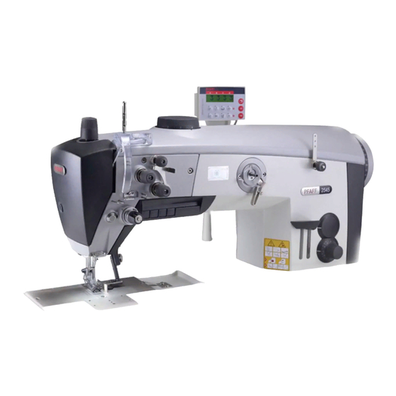
Pfaff POWERline 2545 Adjusiment Manual
Hide thumbs
Also See for POWERline 2545:
- Instruction manual (38 pages) ,
- Setup instructions (38 pages) ,
- Adjustment manual (56 pages)

Related Manuals for Pfaff POWERline 2545


Summary of Contents for Pfaff POWERline 2545
- Page 1 2545 2546 ADJUSTMENT MANUAL This Adjustment Manual is valid for machines from the following serial numbers onwards: # 7 206 577 www.promelectroavtomat.ru 296-12-19 121/002 Justieranleitung Ef. engl. 07 .10...
- Page 2 The reprinting, copying or translation of PFAFF Service Manuals, whether in whole or in part, is only permitted with our previous authorization and with written reference to the source. PFAFF Industriesysteme und Maschinen AG Hans-Geiger-Str. 12 - IG Nord D-67661 Kaiserslautern...
- Page 3 Position et hauteur de l’attrape-fi l ..................29 .06.03 Pression du couteau ......................30 .06.04 Ressort de friction du fi l inférieur ..................31 .06.05 Essai de coupe manuel ......................32 Schéma fonctionel PFAFF 2545/46 PLUS avec PF 321 ............ 34 www.promelectroavtomat.ru...
-
Page 4: Notes On Adjustment
Adjustment Adjustment Please observe all notes from Chapter 1 Safety of the instruction manual! In particular care must be taken to see that all protective devices are refi tted properly after adjustment, see Chapter 1.06 Danger warnings of the instruc- tion manual! If not otherwise stated, the machine must be disconnected from the electrical power supply. - Page 5 Adjustment Adjusting the basic machine Basic position of the balance wheel .05.01 (adjustment aid) Requirement When the needle bar is positioned at t.d.c., the marking "0" on the scale should be level with the top edge of the belt guard (see arrow). 127-01 Fig.
-
Page 6: Balance Weight
Adjustment Balance weight .05.02 Requirement When the needle bar is positioned at b.d.c. (balance wheel position 180°) the largest ec- centricity of the balance weight 1 should be at the top. Fig. 1 - 02 ● Adjust balance weight 1 (screw 2) in accordance with the requirement. www.promelectroavtomat.ru... -
Page 7: Zero Position Of The Unison Feed
Adjustment Zero position of the unison feed .05.03 Requirement When the stitch length is set at "0", the top and bottom feed dogs and the needle bar should not make any feeding motion when the balance wheel is turned. Fig. 1 - 03 ●... -
Page 8: Feeding Motion Of The Unison Feed
Adjustment Feeding motion of the unison feed .05.04 Requirement When the needle bar is positioned at b.d.c. (balance wheel position 180°), and the ma- ximum stitch length is set, the top and bottom feed dogs and the needle bar should not make any feeding motion when the reverse-feed lever is pressed. -
Page 9: Lifting Motion Of The Bottom Feed Dog
Adjustment Lifting motion of the bottom feed dog .05.05 Requirement When the balance wheel is positioned at 180°, the feed dog should be at t.d.c. Fig. 1 - 05 ● Adjust eccentric 1 (screws 2) in accordance with the requirement. Use the kit with the Order No. - Page 10 Adjustment Fig. 1 - 05a Activate lifting movement ● Lifting movement is activated if connection part 8 is swiveled in as shon in fi gures 1 - 05a, and screws 9 (M6 x 16) and 10 (M5 x 16) have been attached. Deactivate lifting movement ●...
-
Page 11: Height Of The Bottom Feed Dog
Adjustment Height of the bottom feed dog .05.06 Requirement 1. When the needle bar is positioned at b.d.c. (balance wheel position 180°), the bottom feed dog should be positioned 0.5 mm horizontally above the top edge of the needle plate, when crank 5 is in the centre of the slot. -
Page 12: Feeding Stroke Difference
Adjustment Feeding stroke difference .05.07 Requirement With the maximum stitch length set, when the balance wheel is turned the feeding stro- kes of the needle and the bottom feed dog should be the same. Fig. 1 - 07 ● With connecting rod 1 (nut 2) increase ("+") or reduce (-) the needle feed stroke in accordance with the requirement. -
Page 13: Preliminary Adjustment Of The Needle Height
Adjustment Preliminary adjustment of the needle height .05.08 Requirement When the needle bar is positioned at t.d.c. (balance wheel position 0°), the clearance between the needle point and the needle plate should be 22 mm. Fig. 1 - 08 ● Without turning it, re-position needle bar 1 (screw 2) in accordance with the requirement. -
Page 14: Needle Rise, Hook Clearance, Needle Height And Needle Guard
Adjustment Needle rise, hook clearance, needle height and needle guard .05.09 Requirement With the stitch length set at "4.5" and in the needle rise position (see table) 1. The hook point 6 should be positioned at "needle centre" with a hook-to-needle clea- rance of 0.05 –... - Page 15 Adjustment ● Adjust needle guard 7 (screw 8) in accordance with requirement 3. If the needle size is changed, a quick adjustment of hook bearing 3 is possible, after loosening screws 4 and 5. www.promelectroavtomat.ru...
-
Page 16: Top Feed Stroke
Adjustment Top feed stroke .05.10 Requirement With adjustment wheel 1 set at "5", the top feed dog 7 and presser foot 4 should each rise by 5.0 mm. Fig. 1 - 10 ● Remove the bottom feed dog and set adjustment wheel 1 at "5". ●... -
Page 17: Top-Feed Lifting Motion
Adjustment Top-feed lifting motion .05.11 Requirement The top feed dog should just have reached the needle plate when the presser foot lift is set at 5 mm and the needle descending from above is 2 mm above the needle plate. Fig. -
Page 18: Adjusting The Potentiometer For Speed Reduction
Adjustment Adjusting the potentiometer for speed reduction .05.12 ● Press "P" on the control panel, while simultaneously switching the machine on. ● Enter the code 3112 via the numbered keys and confi rm by pressing "E". ● Select parameter 501 via the numbered keys and confi rm by pressing "E". ●... -
Page 19: Bobbin Case Opener Stroke
Adjustment Bobbin case opener stroke .05.13 Requirement When the balance wheel is turned 1. The beak 4, when it is at the right point of reversal of the bobbin case opener 1, should rise from the needle plate 5 by the thickness of the thread. 2. -
Page 20: Adjusting The Shortened Trim Stitch
Adjustment Adjusting the shortened trim stitch .05.14 Requirement For the trim stitch the machine should carry out a stitch length of 0.5 – 1.0 mm. Fig. 1 - 14 ● Adjust lever 1 (screws 2) in accordance with the requirement. www.promelectroavtomat.ru... -
Page 21: Bobbin Winder
Adjustment Bobbin winder .05.15 Requirement 1. When the bobbin winder is engaged, the winding spindle must be driven reliably. When it is disengaged, friction wheel 3 should not be touching drive wheel 1. 2. When it is switched off, the bobbin winder must click securely into its end position (knife raised). -
Page 22: Thread Check Spring And Thread Regulator
Adjustment Thread check spring and thread regulator .05.16 Requirement 1. The movement of thread regulator 3 must be completed when the needle point enters the material. 2. When the thread loop is at its largest while being passed around the hook, the check thread spring 3 should rise slightly from the rest 1. -
Page 23: Sewing Foot Pressure
Adjustment Sewing foot pressure .05.17 Requirement The material should be fed properly even at maximum speed and with the smallest stroke. Fig. 1 - 17 ● Turn adjustment wheel 1 in accordance with the requirement. www.promelectroavtomat.ru... - Page 24 Adjustment Lubrication .05.18 Requirement After a running time of 10 seconds a thin fi lm of oil should be visible on paper strip 1 when this is held over the hook. Fig. 1 - 18 ● Check that the machine is fi lled with oil and that the oil lines are free of air. ●...
-
Page 25: Limiting The Stitch Length
Adjustment Limiting the stitch length .05.19 When exch ing the parts kit with stitch lengths differing from the as-deliv- ered state of the machine, limit the max. stitch length using stitch adjuster 4. Fig. 1 - 19 ● Set the desired max. stitch length at control button 1 (on model CN9 = 9.0 mm, on model DN12 = 12 mm) ●... -
Page 26: Speed Reduction
Adjustment Speed reduction .05.20 Requirement If a stitch length longer than 9 mm is set, the speed reduction switch 3 must be pressed. 128-081 Fig. 1 - 20 ● Adjust retaining plate 1 (screws 2) in accordance with the requirement. www.promelectroavtomat.ru... -
Page 27: Re-Engaging The Slip-Clutch
Adjustment Re-engaging the slip-clutch .05.21 Clutch 1 is adjusted at the works. In the case of a thread jamming, clutch 1 will disengage, in order to avoid damage to the hooks. The following describes how to re-engage clutch 1. Fig. 1 - 21 ●... - Page 28 Adjustment Adjusting the thread trimmer -900/81 Resting position of roller lever/radial position of control cam .06.01 Requirement 1. When the take-up lever is at t.d.c. (balance wheel position 60 °), control cam 1 should just have moved roller lever 5 into its basic position. 2.
-
Page 29: Position And Height Of The Thread Catcher
Adjustment Position and height of the thread catcher .06.02 Requirement When the needle bar is positioned at b.d.c. (balance wheel position 180°) the edges of thread catcher 3 and knife 5 should be fl ush (see arrow). 127-096 Fig. 1 - 23 ●... -
Page 30: Knife Pressure
Adjustment Knife pressure .06.03 Requirement When the front edge of thread catcher 3 is 5 – 6 mm in front of the knife blade, the knife 4 should be touching the catcher edge with slight pressure. Fig. 1 - 24 ●... -
Page 31: Bobbin Thread Clamp Spring
Adjustment Bobbin thread clamp spring .06.04 Requirement When the thread trimmer is in its cutting position, the clamp spring should slightly touch the thread catcher and hold the thread reliably. Fig. 1 - 25 ● Adjust clamp spring 1 (screw 2) in accordance with the requirement. ●... -
Page 32: Manual Cutting Test
Adjustment Manual cutting test .06.05 Requirement 1. 1. When moving forward, thread catcher 1 must not move bobbin thread 3 2. When thread catcher 1 is at its front point of reversal, bobbin thread 3 should be in the centre of the marked area (see arrow). 3. - Page 33 Adjustment Consult the instruction manual for the drive for a description of the parameter settings and a list of the parameters. www.promelectroavtomat.ru...
- Page 34 Block diagram Block diagram PFAFF 2545/46 PLUS with PF 321 PD 6 2545 / 46 Y3, Y4, Y5, Y6, Y8, Y14, Y1X, R1 (Option) (Option) Adapter Adapter 1113229 B 41 B 80 ST 2 B 18 B 776 for Software...
- Page 35 Note www.promelectroavtomat.ru...
- Page 36 PFAFF Industriesysteme und Maschinen AG Hans-Geiger-Str. 12 - IG Nord D-67661 Kaiserslautern Phone: +49 - 6301 3205 - 0 Fax: +49 - 6301 3205 1386 E-mail: info@pfaff-industrial.com Hotlines: Technical service: +49 - 175/2243-101 Application consultance: +49 - 175/2243-102 Spare-parts hotline: +49 - 175/2243-103 www.promelectroavtomat.ru...
Need help?
Do you have a question about the POWERline 2545 and is the answer not in the manual?
Questions and answers
where can I buy Pfaff 2545 sewing machine parts?