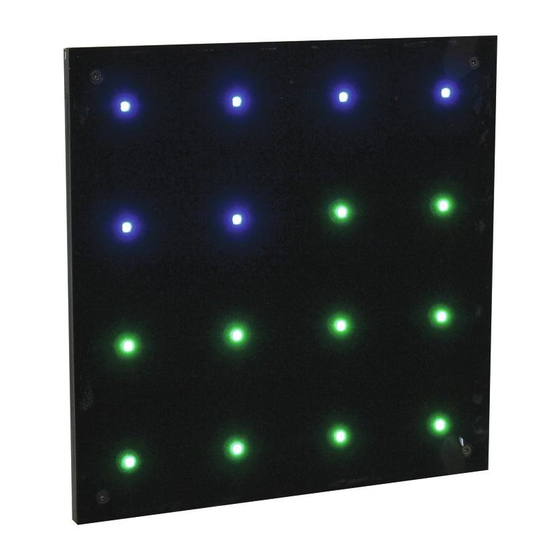
Summary of Contents for EuroLite LED Pixel Panel 16 DMX
- Page 1 BEDIENUNGSANLEITUNG USER MANUAL LED Pixel Panel 16 DMX © Für weiteren Gebrauch aufbewahren! Copyright Keep this manual for future needs! Nachdruck verboten! Reproduction prohibited!
- Page 2 Diese Bedienungsanleitung gilt für die Artikelnummer / This user manual is valid for the article number: 51928739 Das neueste Update dieser Bedienungsanleitung finden Sie im Internet unter: You can find the latest update of this user manual in the Internet under: www.eurolite.de 2/28 00049912.DOC, Version 1.4...
-
Page 3: Safety Instructions
- download the latest version of the user manual from the Internet INTRODUCTION Thank you for having chosen a EUROLITE LED Pixel Panel 16 DMX. If you follow the instructions given in this manual, we are sure that you will enjoy this device for a long period of time. -
Page 4: Health Hazard
This device falls under protection-class I. The power plug must only be plugged into a protection class I outlet. The voltage and frequency must exactly be the same as stated on the device. Wrong voltages or power outlets can lead to the destruction of the device and to mortal electrical shock. Always plug in the power plug last. -
Page 5: Description Of The Device
This device must never be operated or stockpiled in surroundings where splash water, rain, moisture or fog may harm the device. Moisture or very high humidity can reduce the insulation and lead to mortal electrical shocks. When using smoke machines, make sure that the device is never exposed to the direct smoke jet and is installed in a distance of 0.5 meters between smoke machine and device. - Page 6 Overview Front Rear DMX ADDRESS 32 64 128 256 LIGHTING CONTROL PROTOCOL DMX512 XLR occupation: 1: Ground 2: Signal (-) 3: Signal (+) 1. Fixation screws of the cover plate 2. Individually controlable tricolor LEDs 3. DMX OUT 4. Power OUT 5.
-
Page 7: Overhead Rigging
Overhead rigging DANGER TO LIFE! Please consider the EN 60598-2-17and the respective national standards during the installation! The installation must only be carried out by an authorized dealer! The installation of the device has to be built and constructed in a way that it can hold 10 times the weight for 1 hour without any harming deformation. -
Page 8: Fixed Installation
The maximum drop distance must never exceed 20 cm. A safety bond which already held the strain of a crash or which is defective must not be used again. DANGER TO LIFE! Before taking into operation for the first time, the installation has to be approved by an expert! Fixed Installation Before attaching the device, make sure that the installation area can hold a minimum point load of 10 times the device's weight. -
Page 9: Master/Slave Operation
Occupation of the XLR connection: If you are using controllers with this occupation, you can connect the DMX output of the controller directly with the DMX input of the first device in the DMX chain. If you wish to connect DMX controllers with other XLR outputs, you need to use adapter cables. -
Page 10: Connection Between Devices
Connection between devices There is a power output connector and a power input plug on the rear panel. Connect one output with the input of the next fixture until all fixtures are connected. Please note: A maximum of 8 LED Pixel Panels may be linked together. After every 8 LED Pixel Panels, the fixtures must have a renewed connection with the power mains. -
Page 11: Program Selection
Blackout In order to select Blackout, set DIP switch 10 to ON and DIP switch 1 to 9 to OFF. Program Selection Internal Programs Green Yellow Blue Violet Cyan White Red-green-red-green Red-blue-red-blue Green-green-violet-violet Red-red-blue-blue White-off-white-off Red-off-red-off Red-red-blue-blue Green-green-violet-violet 7-Color fade all LEDs simultaneously 7-Color fade each LED individually... -
Page 12: Addressing The Device
Addressing the device Each device occupies 48 channels. To ensure that the control signals are properly directed to each device, the device requires addressing. This is to be adjusted for every single device by changing the DIP-switches. The starting address is defined as the first channel from which the device will respond to the controller. Please make sure that you do not have any overlapping channels in order to control each device correctly and independently from any other fixture on the DMX data link. - Page 13 CH 16 CH 17 CH 18 CH 19 CH 20 CH 21 CH 22 CH 23 CH 24 CH 25 CH 26 CH 27 CH 28 CH 29 CH 30 CH 31 CH 32 CH 33 CH 34 CH 35 CH 36 CH 37 CH 38...
-
Page 14: Cleaning And Maintenance
CLEANING AND MAINTENANCE DANGER TO LIFE! Disconnect from mains before starting maintenance operation! We recommend a frequent cleaning of the device. Please use a soft lint-free and moistened cloth. Never use alcohol or solvents! There are no serviceable parts inside the device. Maintenance and service operations are only to be carried out by authorized dealers. - Page 15 DMX ADDRESS 32 64 128 256 LIGHTING CONTROL PROTOCOL DMX512 XLR occupation: 1: Ground 2: Signal (-) 3: Signal (+) Please note: All information is subject to change without prior notice. 15.10.2015 © 28/28 00049912.DOC, Version 1.4...


Need help?
Do you have a question about the LED Pixel Panel 16 DMX and is the answer not in the manual?
Questions and answers