
Related Manuals for flamco logoEco A2RXE


Summary of Contents for flamco logoEco A2RXE
- Page 1 Technical information for installation and operation LogoEco Heat Interface Unit (HIU) A2RXE Instantaneous Hot Water & Space Heating...
-
Page 2: Table Of Contents
Contents Symbols and abbreviations Symbols Operation Space heating (SH) Domestic hot water (DHW) Priority switching CAUTION, general safety remark Recycle component if possible General Plumbing Requirements British and Irish standards District heating CAUTION, risk of shock Wrench, manual tool Space heating Domestic water Servicing General Wiring Requirements... -
Page 3: Operation
1. Operation 2. General Plumbing Requirements 1.1 Space heating (SH) the heating system must conform to current building regulations Part L1a. The heat exchanger physically separates the district heating network from the space heating circuit. The application minimizes the risk of contamination of district heating water as well as the risk and consequences of leakage in the space The appliance must be installed in accordance with, and comply to, the current: IEE Regulations, Building Regulations, heating circuit. -
Page 4: District Heating
2. General Plumbing Requirements 2. General Plumbing Requirements 2.3 District heating 2.5 Domestic water (DHW) CAUTION! The DHW circulation pump is an available option within the HIU. The circulation system, connected to the HIU, must not Components, pipes and radiators in, and connected to, the unit may be hot. The heat interface unit is designed for use with centralized heating systems up to 90ºC. -
Page 5: General Wiring Requirements
3. General Wiring Requirements 4. Application These instructions apply in the UK and Ireland only and must be followed except for any statutory obligations. Component The HIU A2RXE is used to provide domestic hot water and space heating in residences connected to a district heating system. -
Page 6: Facts And Figures
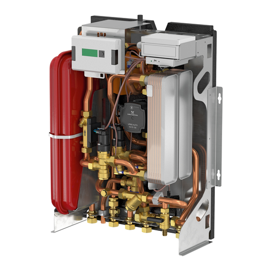
5.1 Facts And Figures Strainer Flow temperature Sensor (primary) 16 30 29 Flow temperature Sensor (heat meter) Secondary (DHW) = District Heating = Domestic Hot Water Test point (primary, return) = Space Heating Δp ∆p = Differential Pressure (kPa) Heat meter = Flow Rate (l/s) Control valve (DHW) = Temperature (ºC) -
Page 7: Installation
6. Installation 6. Installation Positioning 55 80 60 60 120 60 Preparation - First Fix Rail (FFR) Mounting to the wall Additional items required The wall needs to be strong enough to First Fix Rail support the HIU. If the wall is of drywall construction make sure that there is a board installed (e.g. -
Page 8: Service
6. Installation 7. Service Installation 7.1 Filling the SH CAUTION! Please use caution when handling the HIU. Parts and components may be hot or energized. Contact may lead to shock, burn or electrocution. 1. Disconnect the HIU from the mains power. 2. - Page 9 7. Service 7. Service 7.2 Bleeding the air 7.3 Call for Space Heating (SH) All air has to be removed from the system to ensure full functionality of the SH. Bleeding the air can be either manually (1) The unit can be connected to a room thermostat or a timer/heating or automatically (2).
-
Page 10: Power Supply
7. Service 7. Service 7.4 Power supply 7.5 Commissioning The HIU is equipped with an electric connection box that converts the 230VAC Follow the steps shown below to commission the HIU. If leakage or other faults should occur, go to chapter “Troubleshoot”. power supply to 24 VDC and powers the equipped SH pump and optional insulated DHW pump. -
Page 11: Removing And Securing The Case
7. Service 7. Service Removing and securing the case 7.7 Grundfos pump The case of the HIU is secured by the mounting bracket of the heat meter display and a screw through the top of the HIU. The Grundfos pump has 3 control modes (proportional pressure, constant pressure and constant curve). Each control mode has 4 settings to choose from. -
Page 12: Hot Water Circulation
7. Service 7. Service 7.9 Hot Water Circulation The domestic hot water circulation pump is an available option within the unit. The pump is added to minimize delay in the delivery of domestic hot water at the draw pressure control valve is set at its maximum of 60 kPa (default setting). Adjustments to the pump settings should be done by authorised personnel only. -
Page 13: Heat Meter
7. Service 7. Service 7.11 Heat Meter 7.12 Troubleshoot (technician) Complaint LED indication light Cause Solution functionality. You can scroll through the menu by shortly pressing the black button next to the display. The serial number (8 Leakage digit number) can be found as shown in the picture. Coupling nut shows leakage Coupling nut is loose Fasten coupling nut... - Page 14 Units (HIU) Complaint LED indication light Cause Solution Flamco Limited prides itself on bringing to the UK market a proven range of Heating and Cooling Interface Units. To ensure No DHW No DHW No water pressure Check/open main water supply valve both the primary and secondary side of the heat network are designed, installed and commissioned to realise the desired heating comfort levels.
- Page 15 8. Appendix A 8. Appendix A 8.5 Recommendations for system conditioning - (Basic process) • “PH” or relative Acidity/ Alkalinity are of key importance in managing the production of system corrosion. It is • recommended that PH Level of the system water be between 7 and 8.5 (ideally 7.4/7.5). A Lower PH level than Compliance Guide.
- Page 16 8. Appendix A 8. Appendix B Example wiring of a pre-payment system (GURU Systems) It is recommended that a regime of periodic inspection of the system be undertaken. The inspection shall take the form of: Pulse Output System visual inspection, exterior corrosion, water stains on the pipe work and equipment, suggesting a slow leak and Pulse make up water entering the system thereby diluting the inhibitor concentrations.
- Page 17 8. Appendix C Spare parts Spare parts Description Detail 1 & 28 Y Strainer G3/4” BT x G3/4” BT L=82 PN20 2 & 20 Temperature sensor NTC 10K3 1/8”BSP ø4.7x17 4 & 5 Pressure test point Spool piece 110mm G 3/4” x G 3/4” 8 &...
- Page 18 Notes Contact United Kingdom Flamco Limited Washway Lane St Helens Merseyside WA10 6PB United Kingdom +44 1744 744 744...
- Page 19 Flamco Limited Washway Lane WA10 6PB St. Helens Merseyside United Kingdom T +44 17 447 447 44 F +44 17 447 447 00...
Need help?
Do you have a question about the logoEco A2RXE and is the answer not in the manual?
Questions and answers