
Related Manuals for Resol DeltaSol BS


Summary of Contents for Resol DeltaSol BS
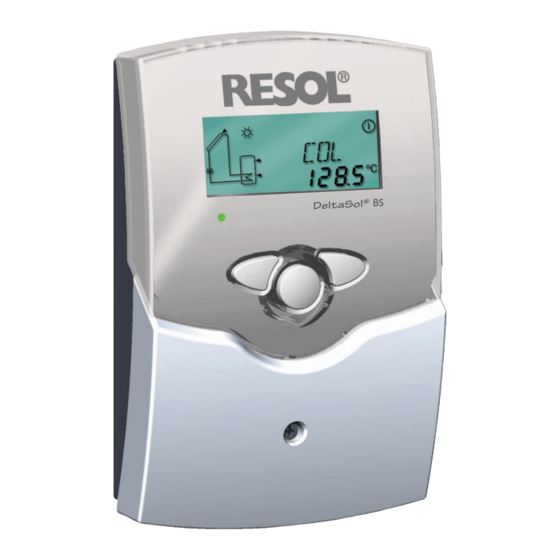
- Page 1 ® RESOL DeltaSol Mounting Connection Handling Fault localization Examples manual Thanks for buying a RESOL. Read this manual carefully to get the best perfomance from this unit. www.resol.de...
-
Page 2: Table Of Contents
Please the approval of RESOL - Elektronische Regelungen GmbH. observe that the mounting is adapted to the characteristics This especially applies for copies, translations, micro films of the building, that the local regulations are respected and and the storage into electronic systems. -
Page 3: Technichal Data And Function Survey
DeltaSol ® • system-monitoring-display • up to 4 temperature sensors Pt1000 • heat balancing • function control • user-friendly operation by simple handling • pump speed control, solar ope- rating hours counter and ther- mostat function optionally Scope of delivery: 1 x DeltaSol ®... - Page 4 DeltaSol ® 1.2.1 Allocation of clamps for system 1 Standard solar system with 1 store, 1 pump and 3 sen- sors. The sensor S4 / TRF can optionally be used for heat quantity balancing. Arr 1 Symbol Specification Collector sensor Store sensor below Store sensor at the top (optionally)
-
Page 5: Electrical Wiring
3 Temperature sensors Pt1000 (1 x FKP6, 2 x FRP6) 115 420 90 Accessory Overvoltage protection It is highly recommended to connect this RESOL overvoltage protection SP1 to all collector sensors in order to avoid overvoltages (e.g. by lightning). RESOL SP1 180 110 10... -
Page 6: Installation
DeltaSol ® Installation display Warning! 1.1 Mounting Switch-off power supply before opening the housing. The unit must only be located internally. It is not suitable for installation in hazardous locations and should not be cover sited near to any electromagnetic field.The controller must additionally be equipped with an all-polar gap of at least 3 mm pushbutton or with a gap according to the valid installaton regulations,... -
Page 7: Operation And Function
DeltaSol ® Operation and function 2.1 Pushbuttons for adjustment The controller is operated by 3 pushbuttons below the display. The forward-key (1) is used for scrolling forward through the indication menu or to increase the adjustment values. The backwards-key (2) is accordingly used for the reverse function. -
Page 8: System Screen
DeltaSol ® 2.2.3 System screen The system screen (active system scheme) shows the schemes selected on the controller. It consists of several system component symbols, which are - depending on the current status of the system - either flashing, permanently shown or hidden. -
Page 9: Commissioning
DeltaSol ® 3. Commissioning On commissioning you have to adjust primarily the matching system 1.Ac power supply must be activated.The controller passes an initialisation phase in which the operating control lamp Operation cont- flashes red and green.After having finished the initialisation, rol lamp the controller is in automatic operation with factory set- tings.The preadjusted system scheme is Arr 1. -
Page 10: Control Parameter And Indication Channels
DeltaSol ® Controller parameter and indication channels 4.1 Channel-overview Legend: Corresponding channel is only available if the option heat Corresponding channel is available. quantity measurement is activated (OWMZ). Corresponding channel is available if the appropriate option Corresponding channel is only available if the option heat is activated. -
Page 11: Indication Channels
DeltaSol ® 4.1.1 Indicataion of collector temperatures Shows the current collector temperature. COL: Collector temperature • COL : collector temperature (1-collector-system) display range: -40 ...+250 °C 4.1.2 Indication of store temperatures Shows the current store temperature. TST,TSTL,TSTU: Store temperatures • TST : store temperature (1-store-system) Display range: -40 ...+250 °C •... -
Page 12: Adjustment Channels
DeltaSol ® 4.1.7 Heat quantity balancing OHQM:Heat quantity balan- A heat quantity balancing is possible for all systems in cing conjunction with a flowmeter.You just have to activate the Adjustment range: OFF ...ON option heat quantity balancing in the channel OHQM. Factory setting: OFF The volume flow readable at the flowmeter (l/min) must FMAX:... - Page 13 DeltaSol ® 4.1.8 ∆T -regulation DT O: Primarily the controller works in the same way as a standard Switch-on temperature differential controller. If the switch-on difference (DT O) Adjustment range 1,0...20,0 K is reached, the pump is activated and after having got an Factory setting 6.0 impulse (10 s) a minimum pump speed (nMN = 30 %) is run.
- Page 14 (R1/R2) is deactivated in order to avoid a damaging overheating of the solar components (collector emergency shutdown).The limit temperature is set to 140 °C by RESOL but it can be changed within the adjustment range Limit collector temperature of 110 ...200 °C. In the display is shown (flashing).
- Page 15 DeltaSol ® 4.1.14 Recooling function If the adjustem maximum store temperature (S MX) is reached, the solar pump remains activated in order OREC: to avoid an overheating of the collector. The store option recooling temperature might continue to increase but only up to adjustment range 95 °C (emergency shutdown of the store).
- Page 16 DeltaSol ® 4.1.17 Pump speed control A relative minimum pump speed is specified for pumps nMN: connected at the outputs R1 and R2 via adjustment channel Pump speed control nMN. Adjustment range: Attention: 30 ...100 Factory setting: 30 When using consumers (e.g. valves) which are not (PG 67.30 and PG 69.30) pump speed controlled, the value must be adjusted to 100 % in order to deactivate the pump speed...
-
Page 17: Tips For Fault Localization
DeltaSol ® 5.Tips for fault localization can fuse T4A If a malfunction occurs, a notification is given on the display of the controller: 220 ... 240 V~ 2 (1) A (220 ... 240) V~ Temp. Sensor 2 (1) A (220 ... 240) V~ Warning symbol Pt1000 Operating control lamp... -
Page 18: Miscellaneous
DeltaSol ® 5.1Various: Pump is overheated, but no heat transfer from collector Pump starts for a short moment, switches-off, switches-on to the store, feed flow and return flow are equally warm, again, etc. („controller hunting“) perhaps also bubble in the lines. Air in the system? Is the temperature diffe- Exhaust the system;... - Page 19 DeltaSol ® Stores are cooled during the night. Control the return flow Please also check further preventer in warm water pumps which are connec- circulation- o.k. ted to the solar store. Does collector circuit pump run during the night? Check the controller Cleaning or replacement.
-
Page 20: Accessory
Overvoltage protection We highly recommend to install the RESOL overvoltage protection in order to avoid overvoltage damages at the collector (e.g. by lightening). Flowmeter If you are interested in realising a heat quantity balancing, you need a flowmeter for measuring the volume flow in...
Need help?
Do you have a question about the DeltaSol BS and is the answer not in the manual?
Questions and answers