
Related Manuals for Gree NCHS1D


Summary of Contents for Gree NCHS1D
- Page 1 Owner's Manual Original Instructions Commercial Air Conditioners GMV6 HR Mode Exchange Box Models: NCHS1D NCHS2D NCHS4D NCHS8D...
- Page 2 (7) The final right to interpret for this instruction manual belongs to Gree Electric Appliances Inc. of Zhuhai.
- Page 3 Exception Clauses Manufacturer will bear no responsibilities when personal injury or property loss is caused by the following reasons: (1) Damage the product due to improper use or misuse of the product; (2) Alter, change, maintain or use the product with other equipment without abiding by the instruction manual of manufacturer;...
-
Page 4: Table Of Contents
Contents 1 Safety Notices (Please be Sure to Abide) ·························································· 1 2 Product Introduction ······················································································ 4 2.1 Names of Main Parts ························································································ 4 2.2 Parameter Table ······························································································ 5 3 Preparation before Installation ········································································ 6 3.1 Standard Accessory ························································································· 6 3.2 Installation Site································································································ 7 3.3 Selection Requirement for Communication Wire ·····················································... -
Page 5: Safety Notices (Please Be Sure To Abide)
GMV6 HR Mode Exchange Box 1 Safety Notices (Please be Sure to Abide) WARNING: If not abide strictly, it may cause severe damage to the unit or the people. NOTICE: If not abide strictly, it may cause slight or medium damage to the unit or the people. - Page 6 GMV6 HR Mode Exchange Box R410A refrigerant can Please use specialized produce poisonous gas once accessories or parts to carry it meets fire, so please out installation, or water ventilate the room leakage, electric shock, fire immediately if refrigerant hazard may resulted. leaks out during installation.
- Page 7 Gree Electric Appliances, Inc. of Zhuhai will not assume responsibility for any personal injury or property loss caused by improper installation, improper debugging, unnecessary repair or not following the instructions of this manual.
-
Page 8: Product Introduction
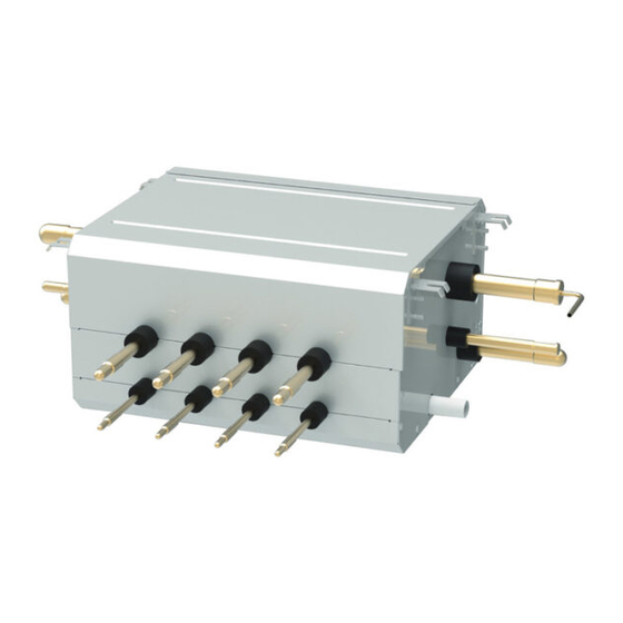
GMV6 HR Mode Exchange Box 2 Product Introduction 2.1 Names of Main Parts One-to-one Mode Exchange Box: Fig.2.1.1 One-to-two Mode Exchange Box: Fig.2.1.2 One-to-four Mode Exchange Box: Fig.2.1.3... -
Page 9: Parameter Table
GMV6 HR Mode Exchange Box One-to-eight Mode Exchange Box: Fig.2.1.4 2.2 Parameter Table Model NCHS1D NCHS2D NCHS4D NCHS8D Numbers of branches unit Per branch unit Maximum numbers of connectable IDUs Total unit Per branch Maximum capacity of connectable IDUs Total... -
Page 10: Preparation Before Installation
The sizes of both nozzles are IDΦ19.3mm and Φ19.05mm, nozzle Φ19 mm Silencer 1 is used for connecting the high pressure gas pipe of NCHS1D and NCHS2D. The sizes of both nozzles are IDΦ22.6mm and Φ22.2mm,nozzle Φ28mm Silencer 2 is used for connecting the low pressure gas pipe of NCHS1D and NCHS2D. -
Page 11: Installation Site
GMV6 HR Mode Exchange Box 3.2 Installation Site (1) Make sure the hanging parts can hold the weight of unit. (2) Water can be drained out from the drainage hose conveniently. (3) No obstacles at outlet and inlets. Keep the air ventilation in good condition. (4) Connect either left or right side of converter to outdoor unit for piping according to installation space, as shown in the Fig.3.2.1, the space used for maintenance should be ensured. - Page 12 GMV6 HR Mode Exchange Box Communication Wire between Mode Exchange Box and indoor unit, outdoor unit: Fig.3.3.1 Total length of communication Wire wire between Mode Exchange Material Type of wire diameter Remarks Box and another standard indoor/outdoor unit L(m) 1. If the wire diameter is enlarged to 2×1mm , the total communication length can reach 1500m.
-
Page 13: Wiring Requirement
Min sectional Min sectional Model Power air switch area for earthing area for power wire (mm cord(mm NCHS1D 220-240V ~50/60Hz NCHS2D 220-240V ~50/60Hz NCHS4D 220-240V ~50/60Hz NCHS8D 220-240V ~50/60Hz NOTES! ① Above circuit breaker and power cord specification are selected according to the max power (max current). -
Page 14: Installation Instruction
GMV6 HR Mode Exchange Box 4 Installation Instruction 4.1 Installation of Mode Exchange Box 4.1.1 Dimension of Outdoor Unit and Mounting Hole Position After the unit is installed, a maintenance port should be reserved at the electric box side of unit for maintenance. - Page 15 GMV6 HR Mode Exchange Box Due to the structure of installation space, the Mode Exchange Box needs a maintenance port. Please reserve another maintenance port for Mode Exchange Box. Fig.4.1.4 NCHS1D outline and installation dimension: Unit:mm Fig.4.1.5...
- Page 16 GMV6 HR Mode Exchange Box NCHS2D outline and installation dimension: Unit:mm Fig.4.1.6 NCHS4D outline and installation dimension: Unit:mm Fig.4.1.7...
- Page 17 GMV6 HR Mode Exchange Box NCHS8D outline and installation dimension: Unit:mm Fig.4.1.8 4.1.2 Suspend the Mode Exchange Box (1) Drill bolt holes and install bolts 1) Stick the installation template at the installation position flatly, drill 4 holes at the installation position basing on the installation template.
- Page 18 GMV6 HR Mode Exchange Box Fig.4.1.11 (2) Install the Mode Exchange Box temporarily Assemble suspension bolt on the expansion bolt, attach the hanger bracket to the suspension bolt. Be sure to fix it securely by using a nut and washer from upper and lower sides of the hanger bracket.
-
Page 19: Pipe Connection
GMV6 HR Mode Exchange Box Level Fig.4.1.13 Cautions for Installation: ① The Mode Exchange Box must be installed by using hanger rod. During installation, the components must be kept vertically upright according to the indicated direction. ② During installation, enough space shall be considered for removal of the components. The pipe shall not be jammed between the components. - Page 20 GMV6 HR Mode Exchange Box Fig.4.2.1 Take out the two silencers, insert nozzle ODΦ22 mm in silencer 1 to the high pressure gas pipe on the right side of the box, then insert nozzle ODΦ28 mm in silencer 2 to the low pressure gas pipe on the right side of the box, weld them together.
- Page 21 GMV6 HR Mode Exchange Box Take out the two silencers, insert nozzle ODΦ22 mm in silencer 1 to the high pressure gas pipe on the left side of box, then insert nozzle ODΦ28 mm in silencer 2 to the low pressure gas pipe on the left side of box, weld them together.
- Page 22 GMV6 HR Mode Exchange Box (4) As for the unused branches, do not cut the pipes with a pipe cutter to avoid refrigerant leakage. Fig.4.2.6 4.2.3 Precautions for the Installation of Connection Pipe (1) Please comply with the following rules during pipe connection: Connection pipe should be as short as possible, so is the height difference between indoor and outdoor units.
- Page 23 GMV6 HR Mode Exchange Box 1) Aim the flared outlet of copper pipe at the center of screwed center, and then rotate the flared nut with hand. 2) Use moment wrench to rotate the flared nut until you has head a sound of “KATA”. 3) Wrap the connection pipe (not insulated) and joint with sponge and then use plastic adhesive tape to bundle it.
- Page 24 GMV6 HR Mode Exchange Box (2) Manifolds can be laid in the following ways: The length of a straight pipe between two manifolds cannot be less than 500 mm. The length of a straight pipe before the main pipe port of the manifold cannot be less than 500mm. The length of a straight pipe between the branch of the manifold and the IDU cannot be less than 500mm.
- Page 25 GMV6 HR Mode Exchange Box Fig.4.2.12 4) Joints of indoor and outdoor unit should be wrapped with insulating material and leave no gap to surfaces of indoor unit and outdoor unit. See Fig.4.2.13 , Fig.4.2.14 and Fig.4.2.15. Fig.4.2.13 Fig.4.2.14 Fig.4.2.15...
- Page 26 GMV6 HR Mode Exchange Box 5) Thermal insulating material of branches should be the same as that of the pipeline. The attached foam of branches cannot be taken as insulating material. 6) When wrapping the tape, the later circle should cover half of the former one. Don’t wrap the tape too tight, otherwise the insulation effect will be weakened.
- Page 27 GMV6 HR Mode Exchange Box 4.2.7 Size Requirement for Branch Pipe and Piping Take the connection sketch map of single-module system for example. Fig.4.2.17 4.2.7.1 Branch Selection of Mode Exchange Box (“A1, A2”) Select branch of Mode Exchange Box as per total capacity of downstream indoor unit(s). Please refer to the following table.
- Page 28 GMV6 HR Mode Exchange Box Total rated capacity of downstream R410A refrigerant system Model indoor units: X(kW) Y-type branch X≤16 FQ01B/A Piping size between Mode Exchange Box and downstream indoor unit (“b、c、d、g”) Piping size between mode exchange box and downstream indoor unit Total rated capacity of downstream indoor units: X (kW) Gas pipe/mm...
-
Page 29: Installation And Test For Drainage Hose
GMV6 HR Mode Exchange Box Connecting method is as shown in the picture: Fig.4.2.18 4.2.7.4 Branch selection of indoor unit of Mode Exchange Box (“C1”) capacity of downstream indoor R410A refrigerant system Model units: X/kW Y-type branch 16<X≤28 FQ01B/A Size of connection pipe between indoor branch and indoor unit should be consistent with the connection pipe of indoor unit. - Page 30 GMV6 HR Mode Exchange Box (5) The side of drainage hose must be bigger than or equal to the size of drainage piping. (6) Install the drainage hose according to below figure and then perform thermal insulation for it. Incorrect installation may lead to leakage and then moisten indoor furniture and other objects. (7) Purchase the normal hard PVC pipe at local market as for the drainage pipeline.
- Page 31 GMV6 HR Mode Exchange Box Unit:mm Fig.4.3.4 Unit:mm Fig.4.3.5 (5) Install the trap as shown in Fig.4.3.6. (6) One trap should be installed for every unit. (7) Convenience for cleaning trap in the future should be considered when installing it. Fig.4.3.6 (8) Horizontal pipe can’t be connected to the vertical pipe at the same horizontal height.
-
Page 32: Cable Connection
GMV6 HR Mode Exchange Box (9) Drainage pipe should kept 1%~2% gradient downwards. Therefore, install a support bracket every 1000-1500mm. Unit:mm Fig.4.3.10 4.3.3 Test of Drainage System (1) Connect the drain hose to the other drain connection pipe of mode exchange box water tray. Add about 1L of water. -
Page 33: Connection Of Cable And Terminal Of Wiring Board
GMV6 HR Mode Exchange Box ⑦ All wiring must use pressure terminal or single wire. If connect the stranded wire to the wiring board directly, it may cause fire. ⑧ Do not let cable connect refrigerant pipe and compressor or fan. ⑨... -
Page 34: Connect Power Cord
GMV6 HR Mode Exchange Box 5.2 Connect Power Cord NOTE! The Mode Exchange Box in the same system must be supplied power uniformly. Fig.5.2.1 Remark: The maximum quantity “n” of indoor unit is decided by the capacity of indoor unit, please refer to capacity of unit. - Page 35 GMV6 HR Mode Exchange Box One-to-two Mode Exchange Box: Fig.5.2.3 One-to-four Mode Exchange Box: Fig.5.2.4 One-to-eight Mode Exchange Box: Fig.5.2.5...
-
Page 36: Connect Communication Wire Of Indoor Unit And Outdoor Unit
GMV6 HR Mode Exchange Box 5.3 Connect Communication Wire of Indoor Unit and Outdoor Unit (1) Open electric box cover of indoor unit. (2) Pass the communication wire through rubber ring. (3) Connect communication wire to wiring board OD (D1, D2) of outdoor unit of Mode Exchange Box. -
Page 37: Routine Maintenance
GMV6 HR Mode Exchange Box Fig.5.3.3 6 Routine Maintenance CAUTION! ① Only clean the air conditioner after turning off the unit and cutting off the power. Otherwise, it may cause electric shock or injury. ② When cleaning the air conditioner, please stand on the solid platform. ③... -
Page 38: Notice Before Seasonal Use
GMV6 HR Mode Exchange Box 6.1 Notice before Seasonal Use (1) Check whether air inlets and air outlets of indoor and outdoor units are blocked. (2) Check whether ground connection is reliable or not. (3) Check whether the wires are connected well. (4) After getting through power, check whether there’re characters on the screen of wire controller.
Need help?
Do you have a question about the NCHS1D and is the answer not in the manual?
Questions and answers