Table of Contents
Advertisement
Quick Links
Virtual Reality
Vaginal Exam
Model II
LM-095N
Instruction Manual
Thank you for purchasing the Virtual Reality Vaginal Exam Model II.
Please read this instruction manual carefully to ensure correct use of the product,
and store it in a safe place for easy access.
KOKEN CO., LTD.
1-4-14 Koraku, Bunkyo-ku, Tokyo 112-0004 JAPAN
URL:http://www.kokenmpc.co.jp
E-mail:customer@kokenmpc.co.jp
©2015-2021 KOKEN CO.,LTD. C-1-1018-1-01-04
9999
Advertisement
Table of Contents

Related Manuals for KOKEN LM-095N


Summary of Contents for KOKEN LM-095N
- Page 1 Thank you for purchasing the Virtual Reality Vaginal Exam Model II. Please read this instruction manual carefully to ensure correct use of the product, and store it in a safe place for easy access. KOKEN CO., LTD. 1-4-14 Koraku, Bunkyo-ku, Tokyo 112-0004 JAPAN URL:http://www.kokenmpc.co.jp E-mail:customer@kokenmpc.co.jp ©2015-2021 KOKEN CO.,LTD. C-1-1018-1-01-04 9999...
- Page 3 3. Use glycerin to lubricate. Be sure to apply a sufficient amount of lubricant (glycerin) to the model before practicing. Koken is not responsible for deterioration or damage to the model occurring from use of lubricants other than glycerin. When the glycerin provided runs out, use commercially available glycerin.
- Page 4 10. Dropping the model or trakSTAR, or subjecting them to strong impact, could cause damage. 11. Be careful not to excessively bend or twist the finger sensor cables, and avoid stepping on them. Such actions could cause the cables to break. Cables cannot be repaired once they have broken. 12.
- Page 5 Handling and Safety Precautions These precautions should be strictly observed in order to ensure safe, long-term use of the product. Caring for the model after use 1. The vulva for vaginal exam II can be removed from the main body by unscrewing the exclusive screws.
-
Page 6: Table Of Contents
Table of Contents Before Use 1. Outline and Features 2. Names of Parts and Configuration Diagram 3. Installing and Uninstalling the Application on the Computer 1) System Requirements 2) Setting up the Virtual Reality Vaginal Exam Model 3) Installing the Application 4)... -
Page 7: Outline And Features
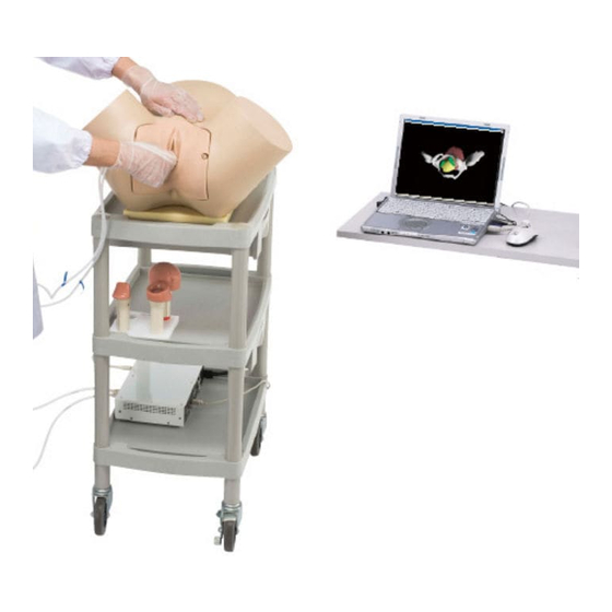
1. Outline and Features Outline The Virtual Reality Vaginal Exam Model makes it possible to see images of the actual movements of the fingers inside the vagina when practicing vaginal examinations, something that has not previously been possible. Instructors can now show trainees specifically how the two fingers should be moved when performing an examination, and can check that the trainee is moving their fingers properly. -
Page 8: Names Of Parts And Configuration Diagram
2. Names of Parts and Configuration Diagram Main body Vulva for vaginal exam II Exclusive screws Base for securing main body Finger sensors trakSTAR (for index finger and second finger) ... - Page 9 Gloves Product key Product CD Plastic wagon Cloth cover *Finger sensors are available in three finger sizes: S, M and L. The S, M and L finger sack sizes are equivalent to surgical glove sizes 6, 7 and 8. * trakSTAR is a trademark of Ascension Technology Corporation.
-
Page 10: Installing And Uninstalling The Application On The Computer
3. Installing and Uninstalling the Application on the Computer 1) System Requirements Please ensure that the computer to be used meets the following requirements. ■ Computer specifi cations ・ Operating system: Windows 8 (32/64-bit version)/Windows 8.1 (32/64-bit version)/Windows 10 (64-bit version) * Also runs on Windows XP (Service Pack 2 or newer version), Vista (32-bit version), 7 (32/64-bit version), but please note that operating system support has ended. - Page 11 (2) Place the base for securing the main body on the upper level of the plastic wagon, and secure the main body in place. Set the sides of the main body against the reference positions for attaching to the base, and turn the knob to fix it in place. Position for attachment Position for attachment (3) Set the trakSTAR on the lower level of the plastic wagon, and insert the cable coming from the...
- Page 12 *Follow the outlines below when connecting and disconnecting the finger sensors. *Follow the outlines below when connecting and disconnecting the finger sensors. < Connecting > < Connecting > Hold the part of the connector circled in blue in the figure below, and connect it to the trakSTAR. *Follow the outlines below when connecting and disconnecting the finger sensors.
- Page 13 (5) Connect the USB cable to the computer. The USB cable connects to the terminal labeled “USB” at the back of the trakSTAR. *The Virtual Reality Vaginal Exam Model will not function if the USB cable is inserted into any location other than the USB port on the computer to which the cable was connected at the time of installation.
-
Page 14: 3) Installing The Application
3) Installing the application (1) After connecting the model, turn the computer on and insert the product CD into the computer. (2) When the product CD is opened, the screen shown in the figure below is displayed. Double-click on [940041 _ RevE]. (3) Double-click on [Setup.exe] to run. - Page 15 Click here (5) The following screen appears. Click [Next]. Click here (6) Select “Just me” and click [Next]. Select “Just me” Click here...
- Page 16 (7) The following screen appears. Click [Next]. Click here (8) The Installation screen appears, and installation commences. (9) When message appears on the screen whether you wish to install or not, please click [Install].
- Page 17 (10) The following screen appears. Click [Next]. Click here (11) The following screen appears. Click [Close]. Click here (12) Turn on the power to the trakSTAR. Power switch (13) Please insert the product key to USB port on the computer.
- Page 18 (14) When the product CD folder is opened, the folders shown in the figure below will appear on the screen. Double-click on [English] or [Japanese] to select the language to be displayed when operating the Virtual Reality Vaginal Exam Model. (15) When the language is selected, the following screen appears.
- Page 19 ○ [Folder] edit box Specify the installation destination. Write a new installation destination to change the installation folder. ○ Change user radio button Select whether to allow only the user performing the installation or all users who uses the computer to use the Virtual Reality Vaginal Exam launch shortcut created during installation. (18) Click [Next] to move to the Confirm Installation screen.
- Page 20 Click here (21) After completing installation, the Installation Complete screen appears. Click the [Close] button to close the screen and complete installation. Click here (22) When installation ends, shortcuts are created on the Start Menu and on the Desktop.
- Page 21 デスクトップ スタートメニュー (23) To install the driver of the product key, enter “Windows key + R”. When the following screen 品キーのドライバーをインストールします。インストールのために「Windows キー+R」を入力 appears, enter “cmd”. て、表示された画面に「cmd」と入力します。 (24) After the product CD is opened, haspdinst.exe file appears. aspdinst.exe ファイルが入っています。 ご使用の前に イルを CMD 画面にドラッグ&ドロップすると、下図下線部分のように、自動的 Drag and drop the haspdinst.exe file to the CMD screen so that a password is automatically entered (24) 製品...
- Page 22 ※ 「-i」の前にスペースを入力していない場合はインストールが実行されず、下図のように 「Operation successfully completed.」と表示されません。 ※ 「-i」を入力し Enter キーを押すと PC 再起動の指示が表示される場合があります。その場合 PC を再起動し、1.から再度インストールを行ってください。 If an error occurs during the installation as shown in the figure below, uninstall the installed driver もしインストール中に下図のようなエラーが発生した場合には、既存のインストールされたドラ and try again. (See p. 21, “Deleting the driver”) イバーをアンインストールしてから再インストールする必要があります。...
- Page 23 用の前に Deleting the driver ドライバーの削除方法 (1) To delete the driver, enter “Windows key + R”. When the following screen appears, enter “cmd”. ドライバーの削除のために、「Windows キー+R」を入力して、表示された画面に「cmd」と入力し ます。 ご使用の前に ドライバーの削除方法 (1) ドライバーの削除のために、「Windows キー+R」を入力して、表示された画面に「cmd」と入力し ます。 削除方法 の削除のために、「Windows キー+R」を入力して、表示された画面に「cmd」と入力し haspdinst.exe ファイルを CMD 画面にドラッグ&ドロップすると、下図下線部分のように、自動 的にそのパスが入力されます。自動的に入力されたパスの後ろに「 -purge -r」を入力して (2) Drag and drop the haspdinst.exe file to the CMD screen so that a password is automatically Enter キーを押すと削除が実行され、下図のように完了のダイアログが表示されます。...
- Page 24 ご使用の前に (4) 下図のような画面が表示されたら、「Y」を押して続行します。 (4) When the screen shown in the figure below appears, click “Y”. (5) After the driver has been deleted, install the driver again. (5) ドライバーの削除が完了したら、ドライバーを再インストールしてください。...
-
Page 25: 4) Installing The Application (Other Methods)
4) Installing the application (other methods) ※ Install the application using this procedure if installation using the procedure described in Section (3) “Installing the application” on p. 12 is unsuccessful. (1) Open the product CD, and double-click on [940041 _ RevE]. (2) Double-click on “Install.msi”. -
Page 26: Setting Up And Exiting The Virtual Reality Vaginal Exam Model
4. Setting Up and Exiting the Virtual Reality Vaginal Exam Model 1) Setting up the Virtual Reality Vaginal Exam Model Connect the base for securing the main body, the main body, the trakSTAR, finger sensors, computer, and product key according to the instructions in Section 2 on p. 8, “Setting up the Virtual Reality Vaginal Exam Model,”... -
Page 27: Fetal Head Rotation 3D Graphics Operation
5. Fetal Head Rotation 3D Graphics Operation 1) Launching the Fetal Head Rotation 3D Graphics application After launching the menu by following the instructions on p. 20, click the [Fetal Head Rotation 3D Graphics] button to launch the Fetal Head Rotation 3D Graphics application. 2) Animation operation Animation operations are performed using the menu at the bottom of the screen. -
Page 28: 3) Viewpoint Operation
(4) Abdomen side of (5) Back side of (2) Right side of main (1) Feet of main (3) Left side of main body body main body main body body (4) Abdomen side of (5) Back side of (2) Right side of main (1) Feet of main (3) Left side of main body body main body main body body (2) Playback adjustment area (4) Abdomen side of (2) Right side of main ... - Page 29 (2) The view rotates perpendicular to the drag direction. Dragging upward zooms in Drag direction: upward Dragging upward zooms in Drag direction: upward Drag direction: downward Dragging downward Drag direction: downward zooms out Dragging downward zooms out (3) Dragging with the left mouse button while holding down the [SHIFT] key: Parallel movement The image moves ...
-
Page 30: Setting Up The Virtual Vaginal Exam
6. Setting Up the Virtual Vaginal Exam (1) To set up the Virtual Reality Vaginal Exam Model, connect the base for securing the main body, the main body, trakSTAR, finger sensors, computer, and product key according to the instructions in Section 2 on p. - Page 31 (5) When the Virtual Vaginal Exam application is launched, the finger sensors are displayed in green on the computer screen as shown below. The fingers on the screen move in accordance with the actual movement of the finger sensors. See Section 1 on p. 29 “Launching the Virtual Vaginal Exam” for instructions on launching the Virtual Vaginal Exam application.
-
Page 32: Handling Of The Virtual Reality Vaginal Exam Model
7. Handling of the Virtual Reality Vaginal Exam Model *This model is made of a special silicone rubber with a feel similar to that of the human body. Please handle it with the same care that you would exercise when working with a human body. 1) Applying lubricant Using a finger, apply a generous amount of glycerin to the vaginal walls and vaginal cavity of the vulva for vaginal exam II, and to the uterus opening of the uterus dilation model that will be... - Page 33 (2) Setting the 8~9 cm uterus dilation model and fetal head model in place These models are set in place in the same way as the 1~2 cm and 3~4 cm uterus dilation models, but have to be aligned with the orientation indicators in the bony birth canal. ...
- Page 34 *Persons within a 1-meter radius of the model, including the trainee, should remove any metallic objects (rings, necklaces, cellular telephones, etc.) about their person before starting to practice. Metallic objects may cause malfunction. *To prevent malfunction of the Virtual Reality Vaginal Exam Model, be sure to place the base that secures the main body on the upper level of the plastic wagon provided as an accessory, and place the trakSTAR on the lower level.
-
Page 35: 8. Basic Operation Of The Virtual Vaginal Exam
8. Basic Operation of the Virtual Vaginal Exam 1 ) Launching the Virtual Vaginal Exam Check that the trakSTAR is turned on, and launch the Virtual Vaginal Exam by clicking the [Virtual Vaginal Exam] button from the menu launched following the instructions on p. 20. When the “Virtual Vaginal Exam”... - Page 36 Select Images This turns the Select Images dialog box display on and off. The Select Images dialog box is used when changing the display of the fetus, pelvis and other elements. For detailed information, see Section 8 -3) -(1) -(a), “ Select Images,” on p. 31. Setup Of Image Details This turns the Setup Of Image Details dialog box display on and off. The Setup Of Image Details dialog box is used when making changes to detailed aspects of the display, such as the transparency or color of the fetus, pelvis or other elements. For detailed information, see Section 8-3) -(1) -(b), “Setup Of Image Details,” on p. 33. Viewpoint This turns the Viewpoint dialog box display on and off. The Viewpoint dialog box is used when changing the viewpoint. For detailed information, see Section 8 -3) -(2), “ Changing the viewpoint,” on p. 35. Measurement This turns the Measurement di alog box display on and off. The Measurement dialog box is used when carrying out distance measurements. For detailed information, see Section 8 -3) -(3), ...
-
Page 37: 3) Operation Of Functions
3) Operation of functions This section explains how to adjust the displayed image, change viewpoints, and measurement the distance between two points. (1)Adjusting the displayed image There are two ways to change the display status of the model: simple Setup, for which the Select Images dialog box is used;... - Page 38 ◯ Uterus model selection This is used to select the uterus model used. Four models are available for selection: the 1~2 cm uterus dilation model; the 3~4 cm uterus dilation model; the 8~9 cm uterus dilation model; and the fetal head model. If the 8~9 cm uterus dilation model or the fetal head model is selected, orientation of the fetus can also be selected.
- Page 39 ◯ Initialization of all Setup This initializes all of the Setup for the “Select Images”, “Setup Of Image Details”, "Viewpoint", "Operation Environment", "Whole Adjustment Of Model" and "Individual Adjustment Of Model” dialog boxes, returning them to the state in which the product was shipped. When the [Initialization of All Setup] button is clicked, a final confirmation dialog box is displayed.
- Page 40 ◯ Transparency level This sets the degree of transparency for the model display. The smaller the value, the more transparent the display. Changing the transparency of the uterus Changing the transparency of the uterus Changing the transparency ◯ Color of the uterus The color in which the model is displayed is set using the "Color Setting" dialog box. ...
- Page 41 (2) Changing the viewpoint The orientation, size, and position of the displayed model can be varied using the mouse or other controls to make it easier to view. (a) Mouse operation To look at the model from a different viewpoint, the mouse is dragged on the screen. The left mouse button is used to rotate the image, while the right mouse button is used to zoom in or zoom out.
- Page 42 (b) Viewpoint dialog box The Viewpoint dialog box is used for parallel movement of the viewpoint, and for zooming in and out. The [Reset Viewpoint] button is used to return to the initial viewpoint. There is no item in the Viewpoint dialog box for rotating the viewpoint, so this should be done using the mouse.
- Page 43 (3) Measurement Distance measurement is carried out using the "Measurement" dialog box, which is displayed by selecting “Display” and then "Measurement" from the menu. With this function, two measurement points are registered, and the distance between them is displayed in centimeter units, to a precision of one decimal place (1 millimeter).
- Page 44 Clicking on the [Measurement] button (or pressing the M key on the keyboard) registers the positions of the two fingers at that point in time as the measurement points. The registered measurement points are displayed in a different color from the temporary measurement points, and a solid line is displayed between the measurement points.
- Page 45 Clicking on the [Measurement] button (or pressing the M key on the keyboard) after moving your finger to the ending point registers the ending point and displays the distance between the starting and ending points. Each time a measurement is made, the result is displayed on the screen as a cumulative display. The [Delete] button can be used to delete results.
-
Page 46: 9. Detailed Configuration Of The Virtual Vaginal Exam
9. Detailed Configuration of the Virtual Vaginal Exam If required, the Operation Environment can be configured and the model display position adjusted. 1) Operation Environment Setup To configure the operation Environment for the application, select "Setup" and then "Operation Environment" from the menu, and use the "Operation Environment Setup" dialog box that is displayed. - Page 47 (2) Light source color The color of the light source is set using the three primary colors: the red component (R); the green component (G); and the blue component (B). Values can be either increased or decreased using the spin buttons next to the component displays, or the color can be selected directly by clicking on [Select Color] to display the "Color Setup”...
- Page 48 (3) Operation Environment Configuring operations and displays "Travel Amount” is used to set the Travel Amount when the viewpoint is operated using the mouse, keyboard or the "Viewpoint" dialog box. The larger the value that is set, the greater the amount of change in the viewpoint for the same operation (the distance that the mouse is dragged, the number of presses of a key on the keyboard or the number of times the button is clicked in the dialog box).
- Page 49 Operation Mode Operation Mode Offset Offset Communication Communication The finger is displayed on the assumption that the sensor will be The finger is displayed on the attached on the fingernail side. assumption that the sensor will be attached on the fingernail side. *1. "Offset" refers to the position of a certain data element expressed as a difference (distance) from a reference point. With this model, the sensor part of the finger sack serves as the data position. * 2.
-
Page 50: 2) Adjusting The Position Of The Model
Reference axis Axis for Position adjustment adjustment Measurement Reference axis Axis for Position adjustment Result adjustment Registration point Measurement Result Registration point 2) Adjusting the position of the model Model position adjustment is a function that allows fine adjustment of the position of the overall model, or of individual positions. - Page 51 ◯ Movement setting This moves the model as a whole from the reference position. The movement distance can be specified for each of the X, Y and Z axis directions. Movement Movement Reference position Reference position ...
- Page 52 ◯ Initialization Clicking on the [Initialize] button resets all the Setup entered for the Whole Adjustment Of Model, including movement, rotation and scale, and returns to the reference position. ◯ Apply The [Apply] button is used to reflect the results after adjustments are made. If the [X] button is clicked to close the dialog box without first clicking the [Apply] button, values will return to the values used prior to adjustment.
- Page 53 ◯ Fetus orientation setting Fetus orientation is selected from among A, RA, RT, RP, P, LP, LT and LA, using the "Orientation” pull- down menu. The orientation can be selected only if the fetus 8~9 cm uterus dilation model and the fetal head model have been selected as the model targeted for adjustment, or if the uterus 8~9 cm uterus dilation model and the fetal head model have been selected as the model for adjustment.
- Page 54 ◯ Initialization Clicking on the [Initialize] button resets all of the Setup entered for the model for adjustment, including movement, rotation and scale, and returns to the reference position. ◯ Apply The [Apply] button is used to reflect the results after adjustments are made. If the [X] button is clicked to close the dialog box without first clicking the [Apply] button, values will return to those values used prior to adjustment.
-
Page 55: Model Configuration Chart
10. Model Configuration Chart Item Quantity Main body 1 Vulva for vaginal exam II 1 Exclusive screws 2 Base for securing main body 1 Finger sensor for index finger (*) 1 Finger sensor for second finger (*) 1 trakSTAR 1 USB cable 1 Power cable 1 ... -
Page 56: Specifications
11. Specifications...
Need help?
Do you have a question about the LM-095N and is the answer not in the manual?
Questions and answers