Table of Contents
Advertisement
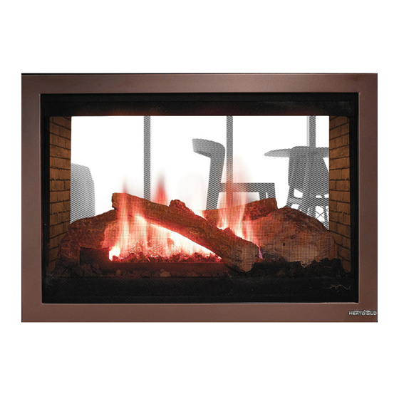
Model:
ST-38GTV
WARNING: IF THE INFORMATION
IN THESE INSTRUCTIONS IS NOT
FOLLOWED EXACTLY, A FIRE OR
EXPLOSION MAY RESULT CAUS-
ING PROPERTY DAMAGE, PER-
SONAL INJURY, OR DEATH.
This product is covered by one or more of the following patents: (United States) 4,112,913; 4,408,594; 4,422,426; 4,424,792; 4,520,791; 4,793,322;
4,852,548; 4,875,464; 5,000,162; 5,016,609; 5,076,254 5,191,877; 5,218,953; 5,328,356; 5,429,495; 5,452,708; 5,542,407; 5,613,487; (Australia)
543790; 586383; (Canada) 1,123,296; 1,297,746; 2,195,264; (Mexico) 97-0457; (New Zealand) 200265; or other U.S. and foreign patents pending.
All manuals and user guides at all-guides.com
1
GUIDE
WARNING: IMPROPER INSTALLA-
TION, ADJUSTMENT, ALTERATION,
SERVICE OR MAINTENANCE CAN
CAUSE INJURY OR PROPERTY DAM-
AGE. REFER TO THIS MANUAL. FOR
ASSISTANCE OR ADDITIONAL INFOR-
MATION CONSULT A QUALIFIED IN-
STALLER, SERVICE AGENCY, OR THE
GAS SUPPLIER.
Please contact your Heat-N-Glo dealer with any
questions or concerns. For the number of your
nearest Heat-N-Glo dealer, please call 952-985-6000.
Printed in U.S.A. Copyright 2001,
Heat-N-Glo, a division of Hearth Technologies Inc.
20802 Kensington Boulevard, Lakeville, MN 55044
Installers Guide
INSTALLERS
Advertisement
Table of Contents

Subscribe to Our Youtube Channel
Related Manuals for Heat-N-Glo ST-38GTV


Summary of Contents for Heat-N-Glo ST-38GTV
- Page 1 ASSISTANCE OR ADDITIONAL INFOR- MATION CONSULT A QUALIFIED IN- STALLER, SERVICE AGENCY, OR THE GAS SUPPLIER. Please contact your Heat-N-Glo dealer with any questions or concerns. For the number of your nearest Heat-N-Glo dealer, please call 952-985-6000. Printed in U.S.A. Copyright 2001, Heat-N-Glo, a division of Hearth Technologies Inc.
-
Page 2: Safety And Warning Information
All manuals and user guides at all-guides.com SAFETY AND WARNING INFORMATION These units MUST use one of the vent systems READ and UNDERSTAND all instructions carefully described in the Installing the Fireplace section of before starting the installation. FAILURE TO the Installers Guide. -
Page 3: Table Of Contents
Appliance Certification............6 Installation Codes ............... 6 High Altitude Installations ............ 6 Section 2: Getting Started ..........7 Introducing the Heat-N-Glo Gas Fireplaces ....... 7 Pre-installation Preparation ..........7 Section 3: Installing the Fireplace ......... 9 Step 1 Locating the Fireplace ......... 9 Step 2 Framing the Fireplace ......... -
Page 4: Service Parts List
All manuals and user guides at all-guides.com Service Parts ST-38GTV Exploded Parts Diagram / Vue éclatée des pièces... - Page 5 All manuals and user guides at all-guides.com ST-38GTV Service Parts List / Liste des pièces de rechange ITEM / SERIAL # / PART NUMBER ENGLISH / FRENCH DESCRIPTION PIÈCE N° DE SÉRIE / N° DE PIÈCE Robertshaw Valve Valve NG / Valve GN...
-
Page 6: Section 1: Approvals And Codes
All manuals and user guides at all-guides.com Approvals and Codes High Altitude Installations Appliance Certification Installers Guide Certification Installation Codes Heat-N-Glo Quality Systems registered by SGS ICS... -
Page 7: Section 2: Getting Started
All manuals and user guides at all-guides.com Getting Started Introducing the Heat-N-Glo Gas Fireplaces Warranty Installers Guide Pre-install Preparation Installers Guide... - Page 8 GAS VALVE VALVE ACCESS PLATE PIEZO IGNITOR TOP LEDGE SPACER PIPE CLAMP VENT COLLAR HOOD 1/2" SPACERS SIDE REFRACTORY GAS VALVE OUTSIDE AIR ACCESS GLASS DOOR LABELS GAS LINE BLOWER GRATE ACCESS ACCESS ELECTRICAL ACCESS Figure 1. Diagram of the ST-38GTV...
-
Page 9: Section 3: Installing The Fireplace
Ceiling* ......... 3 1 ....787 * The clearance to the ceiling is measured from the top of the unit, excluding the stand-offs (see Figure 13). Model ST-38GTV 39 5/8 38 3/4 21 1/16 Inches NOTE: DIMENSIONS SHOWN IN INCHES Vertical Sections. -
Page 10: Step 3 Negative Pressure Make-Up Air
All manuals and user guides at all-guides.com Step 3. Negative Pressure Make-up Air OUTSIDE AIR COLLAR AIR DUCT OUTSIDE AIR COVER PLATE... -
Page 11: Step 4 Installing The Vent System
All manuals and user guides at all-guides.com Step 4. Installing the Vent System A. Vent System Approvals LISTED NON-COMBUSTIBLE TERMINATION CONSTRUCTION LISTED SINGLE-WALL GAS VENT B. System Components. B-TYPE VENT PIPE VENT COLLAR 13 FT. MAXIMUM 10 FT. MINIMUM... -
Page 12: Bedroom Installation In Canada
All manuals and user guides at all-guides.com C. Bedroom Installation in Canada Step 5. Positioning, Leveling, and Securing the Fireplace D. Vent Termination LOWEST DISCHARGE OPENING VENT CAP ROOF PITCH IS X/12 H (MIN.)-MINIMUM HEIGHT FROM ROOF TO LOWEST DISCHARGE OPENING ROOF PITCH H (MIN.) FT. -
Page 13: Step 6 The Gas Controls System
All manuals and user guides at all-guides.com Step 6. The Gas Controls System Standing Pilot Ignition Direct Spark Ignition (DSI). 3/8” (10mm) STANDING PILOT DSI IGNITION IGNITOR 1/2” (13mm) CERAMIC INSULATOR 3/16” (5mm) USE A WRENCH ON SHUT-OFF VALVE WHEN TIGHTENING GAS LINE MANUAL SHUT-OFF VALVE... -
Page 14: Step 8 Gas Pressure Requirements
All manuals and user guides at all-guides.com Step 8. Gas Pressure Requirements Pressure requirements for Heat-N-Glo gas fireplaces are shown in the table below. Pressure Natural Gas Propane Minimum 5.0 inches 11.0 inches Inlet Pressure w.c. w.c. Maximum Inlet 14.0 inches 14.0 inches... - Page 15 All manuals and user guides at all-guides.com 120 VOLT HOUSE WIRING WHITE GROUND BLACK #6 X 1/2" SCREW WALL SWITCH GROUND OR SPEED CONTROL SCREW UPPER WALL JUNCTION MOUNTING BOX (NOT SUPPLIED) BRACKET (B) GROUND SCREW OIL HOLES FIREPLACE JUNCTION BOX BLOWER OUTER MOTOR...
-
Page 16: Step 10 Finishing
All manuals and user guides at all-guides.com Step 10. Finishing Step 11. Installing Trim, Logs & Ember Material CEILING 8" MAXIMUM MANTLE 31” 12" MINIMUM HOOD CAUTION: IF JOINTS BETWEEN THE FINISHED WALLS AND THE FIREPLACE SURROUND (TOP AND SIDES) ARE SEALED, A 300°... -
Page 17: Step 12 Before Lighting The Fireplace
All manuals and user guides at all-guides.com Step 12. Before Lighting the Fireplace Installers Guide EMBER MATERIALS Step 13. Lighting the Fireplace After the Installation... -
Page 18: Section 4: Maintaining And Servicing Your Fireplace
All manuals and user guides at all-guides.com Maintaining and Servicing Your Fireplace Fireplace Maintenance...
Need help?
Do you have a question about the ST-38GTV and is the answer not in the manual?
Questions and answers