Table of Contents
Advertisement
Quick Links
Advertisement
Table of Contents

Related Manuals for Airzone Easyzone AZCE6CB1IAQ


Summary of Contents for Airzone Easyzone AZCE6CB1IAQ
- Page 1 Installation Manual Easyzone...
-
Page 2: Table Of Contents
Connection ___________________________________________________________________________ 11 > Wireless thermostats ___________________________________________________________________ 12 > Elements _____________________________________________________________________________ 12 > Assembly _____________________________________________________________________________ 12 > Airzone Control Gateway-3 Speed Fancoil (AZX6FANCOILZ) ___________________ 13 > Elements _____________________________________________________________________________ 13 > Assembly _____________________________________________________________________________ 13 > Connection ___________________________________________________________________________ 14 > Airzone Control Gateway-0-10 V Fancoil (AZX6010VOLTSZ) ___________________ 15 >... - Page 3 > Elements _____________________________________________________________________________ 25 > Assembly _____________________________________________________________________________ 25 > Connection ___________________________________________________________________________ 26 > Airzone-KNX Integration Gateway (AZX6KNXGTWAY) __________________________ 30 > Elements _____________________________________________________________________________ 30 > Assembly _____________________________________________________________________________ 30 > Connection ___________________________________________________________________________ 30 > Airzone-BACnet Integration Gateway (AZX6BACNET) ___________________________ 31 > Elements _____________________________________________________________________________ 31 >...
- Page 4 > Minimum air adjustment (A-M) ________________________________________________________ 46 SYSTEM ADVANCED SETTINGS __________________________________________________________________ 47 > Airzone Blueface _________________________________________________________________________ 47 > Airzone Think _____________________________________________________________________________ 47 > System parameters ______________________________________________________________________ 48 > Zone parameters _________________________________________________________________________ 50 INCIDENTS ____________________________________________________________________________________________ 51 > Warnings ___________________________________________________________________________________ 51 >...
-
Page 7: Environmental Policy
Environmental Policy • Never dispose of this equipment with household waste. Electrical and electronic products contain substances that can be harmful to the environment if not properly handled. The crossed-out waste bin symbol indicates separate collection of electrical devices, which must be separated from other urban waste. For correct environmental management, at the end of its useful life the equipment should be taken to the collection centers provided for this purpose. -
Page 8: Before Starting
2x0.5 mm wires for power supply). • A Blueface thermostat must be used to enable all the Airzone system functionalities. • Recommendations for the placing of the thermostats: • For equipment using R32 refrigerant, verify the compliance with the local refrigerant regulation. -
Page 9: Elements And Installation
AZ1 - AZ2 - AZ3 The Airzone connection bus is used to connect all the internal elements independent of the main control board and can control up to 8 zones. To connect the Airzone connection bus, there are three 5-pin terminals. This system allows star and bus connection. - Page 10 The automation bus allows several systems to be interconnected in order to manage all of them, using the control peripherals offered by Airzone or their integration into a higher-level control network. To connect the automation bus, there is one 5-pin terminal.
- Page 11 This output can be configured for the control of controlled mechanical ventilation units (CMV) or for the management of a boiler (see Advanced settings section on the Blueface thermostat - System parameters). • CMV configuration Ventilation Cooling Air heating Radiant heating Status Stop Demand ON...
-
Page 12: Temperature Probe (Azx6Sondprotec)
The connection to the external power supply must include a main switch or other method of disconnection that includes a constant separation for all polarities, in accordance with appropriate local and national regulations. The system will automatically restart if the power supply is turned off. Use separate circuits for the unit that is to be controlled and the power supply to the system. -
Page 13: Control Module Of Radiant Elements (Azce6Output8)
Note: To remove the module, pull the tab downwards to release it. Connection The control module of radiant elements is a device that is connected to the Airzone connection bus on the main control board. Relay status LEDs The characteristics of the control relays are Imax 10 A at 110/230 ... - Page 14 The power connection to the module is via a 3-pin terminal . Fix the cables with the screws on the terminal, following the polarity. Once powered, the control module of radiant elements performs a sequential opening and closing of all relay outputs. This operation is repeated once a week to ensure correct operation of the valves.
-
Page 15: Wired Thermostat
AZCE6LITEC For further information, see the technical fact sheet. Assembly Airzone wired thermostats are surface mounted on a support. Remember that the maximum recommended distance for this device is 40 meters. For wall mounting, follow these steps: •... -
Page 16: Wireless Thermostats
AZCE6LITER For further information, see the technical fact sheet. Assembly Airzone wireless thermostats are surface mounted on a support. Remember that the maximum recommended distance for this device is 40 meters. • Remove the back of the thermostat and insert the CR2450 button battery. -
Page 17: Airzone Control Gateway-3 Speed Fancoil (Azx6Fancoilz)
AIRZONE CONTROL GATEWAY-3 SPEED FANCOIL (AZX6FANCOILZ) For further information, see the technical fact sheet. Elements Description Cooling air demand Speed 1 Speed 2 Speed 3 Heating air demand Power supply AC unit bus Assembly This device is DIN rail or wall mounted. This module is externally powered at 110/230 VAC. The location and assembly of this module must comply with current electronic regulations. -
Page 18: Connection
Connection F-Coil F-Coil 2-pipe installation 4-pipe installation The characteristics of the control relays are Imax 10 A at 110/230 VAC voltage free. To control higher power elements, the use of contactors of the power to be controlled is recommended. For connection to the main control board AC unit bus there is one 4-pin terminal. -
Page 19: Airzone Control Gateway-0-10 V Fancoil (Azx6010Voltsz)
AIRZONE CONTROL GATEWAY-0-10 V FANCOIL (AZX- 6010VOLTSZ) For further information, see the technical fact sheet. Elements Description Cooling air demand Heating air demand Ventilation demand Control of fan Power supply AC unit bus Assembly This device is DIN rail or wall mounted. This module is externally powered at 110/230 VAC. The location and assembly of this module must comply with current electronic regulations. -
Page 20: Connection
Connection F-Coil F-Coil 0 W 0 ON/OFF 0 W 0 ON/OFF 2-pipe installation 4-pipe installation The characteristics of the control relays are Imax 10 A at 110/230 VAC voltage free. To control higher power elements, the use of contactors of the power to be controlled is recommended. -
Page 21: Airzone Control Gateway-Electromechanical Unit (Azx6Electromec)
AIRZONE CONTROL GATEWAY-ELECTROMECHANICAL UNIT (AZX6ELEC- TROMEC) For further information, see the technical fact sheet. Elements Description Heating mode Ventilation mode Compressor 2 Compressor 1 Cooling mode Boiler AC unit bus Microswitch Boiler probe Unit probe Assembly This device is DIN rail or wall mounted. This module is powered via the AC unit bus of the main control board. -
Page 22: Connection
Connection O G2 O G1 O Y C1 O 3 4 5 6 7 8 TEMP1 TEMP2 D4 D3 The characteristics of the control relays are 24/48 VAC voltage free. To control higher power elements, the use of contactors of the power to be controlled is recommended. For connection to the main control board AC unit bus there is one 4-pin terminal. - Page 23 The operation logic of the relays is as follows: HVAC Demand Stop Ventilation Cooling air (1 stage) If return temp. < 28°C Cooling air (2 stages) If return temp. > 28°C Heating air (1 stage) If return temp. < 18°C Heating air (2 stage) If return temp.
-
Page 24: Webserver Airzone Cloud
WEBSERVER AIRZONE CLOUD Elements Webserver Airzone Cloud Wi-Fi Dual 2.4-5G (AZX6WSC5GER) For further information, please refer to the technical datasheet. Webserver HUB Airzone Cloud Dual 2.4-5G/Ethernet (AZX6WSPHUB) For further information, please refer to the technical datasheet. Webserver HUB Airzone-Lutron (AZX6WSPLUT) For further information, please refer to the technical datasheet. -
Page 25: Assembly
Assembly The Webserver Airzone Cloud Wi-Fi Dual 2.4-5G (AZX6WSC5GER) is integrated in the domotic bus of the system’s control board or in the external domotic bus of the production control board. It has a 5-pin terminal. Disconnect the terminal to which you wish to connect the Webserver and engage the connector. -
Page 26: Connection
AZX6WSC5GR from a system control board to other system control boards If the Webserver Airzone Cloud is connected to the CCP, use the CCP’s internal domotic bus to connect to the system control board. - Page 27 AZX6WSPxxx from a AX6CCPGAWI to system control units ROUTER (Wi-Fi) - AZX6WSPxxx ROUTER (Ethernet) - AZX6WSPxxx All Airzone systems must be connected to the Internet to provide technical support. - AZX6WSC5GER / AZX6WSPHUB: Only one Webserver per installation needs to be connected (control up to 32 systems).
-
Page 28: Supermaster Controller (Azx6Csmaster [S/E] [B/G])
SUPERMASTER CONTROLLER (AZX6CSMASTER [S/E] [B/G]) Important: This device is not compatible with the production control board (AZX6CCP). Assembly Surface mounted (AZX6CSMASTERS): • Separate the back of the thermostat from the wall support. • Attach the support directly to the wall or by fixing to the switch box. -
Page 29: Production Control Board
PRODUCTION CONTROL BOARD Elements AZX6CCP For further information, see the technical fact sheet. Important: This element is not compatible with supermaster controller (AZX6CSMASTER). For further information, see the technical fact sheet. Important: This element is not compatible with supermaster controller (AZX6CSMASTER). -
Page 30: Connection
Connection Digital inputs The production control board is equipped with 4 digital inputs for external control of Airzone systems. These inputs are configured as normally open. For connection, the use of shielded cable is recommended. DHW: This input activates the DHW mode, whereby all Acuazone/Innobus Pro32 and Flexa 4.0 systems that are working in air heating will stop and display the DHW message on the... - Page 31 Connector bus for air to water gateways The AC unit bus makes it possible to connect various production unit control gateways to the installed air-water unit. To connect these integrated gateways, disconnect the AC unit bus terminal and fit the connector and the gateway fixing post.
- Page 32 Important: In order to optimize the production temperature of the air to water units, the following combinations will not generate air demand in the production control board: - Airzone 3.0 controller gateway (AZX6GTCxxx) in the Flexa 4.0 and Innobus Pro8 system main control boards.
- Page 33 The operation logic of the microswitch is as follows: Meaning Aerothermal 2 pipes 3/4 pipes RadianT* *Only for Airzone RadianT365 system (AZRA6). Once all the connections have been made, make sure the cover of the main control board is correctly replaced.
-
Page 34: Airzone-Knx Integration Gateway (Azx6Knxgtway)
Note: To remove the module, pull the tab downwards to release it. Connection The Airzone-KNX integration gateway is connected to the automation bus on the main control board. To do this, there is one 5-pin terminal. Fix the cables with the screws on the terminal, following the color code. -
Page 35: Airzone-Bacnet Integration Gateway (Azx6Bacnet)
Elements Assembly The Airzone- BACnet integration gateway is integrated in the automation bus on the main control board of the system. It has a 5-pin terminal; disconnect the terminal to which you want to connect the gateway and fit the connector. -
Page 36: Airzone-Lutron Integration Gateway (Azx6Gtilut)
Elements Assembly The Airzone-Lutron integration gateway is integrated in the automation bus on the main control board of the system. It has a 5-pin terminal; disconnect the terminal to which you want to connect the gateway and fit the connector. -
Page 37: Airzone Consumption Meter (Azx6Acccon)
Note: To remove the module, pull the tab downwards to release it. Connection The Airzone consumption meter is an element that is connected by means of an ammeter clamp to the wiring of the outdoor unit to measure the installation's consumption. The power connection to the module is via a 2-pin terminal. -
Page 38: System Installation
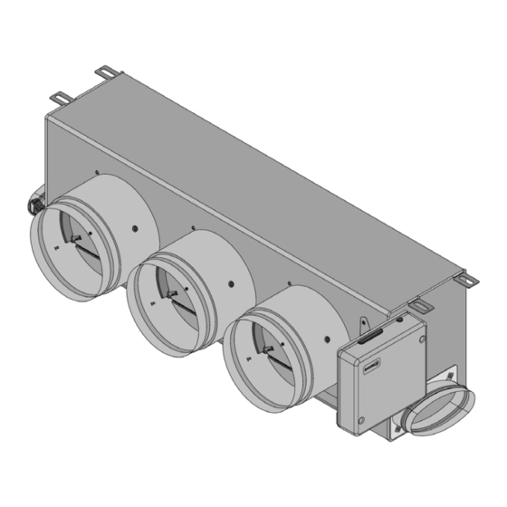
System Installation EASYZONE PLENUM ASSEMBLY Assembly in the indoor unit It is recommended to insulate all metal parts of the Easyzone that remain in contact with the outside to prevent condensation. Locate the drilling holes; if they are covered, use a screwdriver to uncover them to fix the Easyzone to the unit. -
Page 39: Fresh Air Intake (Cmv) Assembly
Remember that the motorized elements are numbered in the following manner: Connect duct from each zone corresponding damper. Follow the instructions for proper insulation. Make a cut in the duct to keep the motor outside. Fresh air intake (CMV) assembly If your Easyzone has CMV and you wish to use this function. -
Page 40: Additional Easyzone Information
ADDITIONAL EASYZONE INFORMATION Bypass damper assembly With a sharp blow, remove the pre-cut area Using a utility knife, remove the insulation on the sides corresponding to the bypass. covering the bypass area and uncover the bypass fixing slots. Fit the bypass damper into the slots and Fix the bypass damper to the plenum turn from left to right until it reaches the using a sheet metal screw (Ø: 3.9 mm). -
Page 41: Motorized Plenum With Blind Cover
Motorized plenum with blind cover Plenums with overridden dampers are manufactured and delivered with the override already done, so the plenums are as follows: For plenums with 7 dampers, the damper that is overridden is no. 8, so when carrying out the initial configuration you must take into account that zone 8 will not be connected. -
Page 42: Thermostat Installation
THERMOSTAT INSTALLATION Remove the back of the thermostat. Fix the back of the thermostat to the wall. Connect the main control board to any of the three terminals AZ1, AZ2 o AZ3. Fix the cables using the main control board turrets. your thermostat wireless... -
Page 43: Power Supply To The System
POWER SUPPLY TO THE SYSTEM Use power supply input to power the main control board at 110/230 VAC as well as any other control elements that require external power supply. Use 3x1.5 mm² cable. To supply power to the main control board, loosen the cable gland if necessary, insert the cable through the hole (Ø: 5 -10 mm) and attach the cables to the terminal... -
Page 44: Checking The Installation
Checking the Installation Check the following items: Status of the main control board LEDs and of the other control elements connected. Consult the Self-diagnostics section on each element's technical fact sheet. The main control board LEDs indicating the opening of motorized elements light up in sequence. -
Page 45: Initial Configuration
Initial Configuration AIRZONE BLUEFACE Languages: Select the zone associated to The system allows you to • Spanish this thermostat. Each zone associate more than one • English has a corresponding control control output to a zone • French output (actuator output or if needed. -
Page 46: Airzone Think
AIRZONE THINK Wireless Think Open wireless association channel. To do so, click SW1. Once opened, have minutes perform the association. You can also open the wireless IMPORTANT: Remember Languages: association channel through not to have more than one • Spanish the Blueface thermostats. - Page 47 The system allows you to associate more than one control Master: Allows the control of output to a zone if needed. It is therefore possible to manage all installation parameters. several control outputs from a single thermostat. Zone: Only allows the control of the zone parameters.
-
Page 48: Airzone Lite
If you want to configure other thermostat settings must access zone advanced settings menu from an Airzone Blueface thermostat. The icon will blink 5 times in green to indicate that the association is correct. If the icon blinks once in red, this indicates... -
Page 49: Checking The Initial Configuration
AC unit-system communication: Set the Airzone system to Stop mode and verify that the AC unit turns off and dampers open. Opening/closing of the dampers and control outputs: Turn on and generate demand in all the zones. -
Page 50: Airflow Regulation
Airflow Regulation Important: Start the airflow adjustment from the central dampers and finalize at damper no. 1. AIRFLOW ADJUSTMENT (REG) Turn on and generate demand in all the zones to open all the dampers. Turn off the zone/damper to be adjusted. Adjust the desired maximum opening with the REG lever (I/II/III/IV). -
Page 51: System Advanced Settings
System Advanced Settings AIRZONE BLUEFACE Press and hold AIRZONE THINK Press and Press and hold hold... -
Page 52: System Parameters
By default, it displays the value 1. The system will show the free address values with a maximum value of 99. If you have address 1 and have an Airzone production control board (AZX6CCP / AZX6CCPWSCC) in the installation, you can use the Supermaster function, which imposes... - Page 53 - Webserver: firmware, IP address, gateway, MAC and PIN. • Reset system. (Only available for Airzone Blueface master thermostats). This allows you to reset the system by returning it to factory settings. To reconfigure the thermostats, go to the Initial configuration section.
-
Page 54: Zone Parameters
ZONE PARAMETERS • Associated outputs. This displays and allows you to select the control outputs associated to the thermostat. • Thermostat settings. This allows you to set up a thermostat as Master or Zone. *Note: It cannot be configured as Master if there is already another thermostat configured as such. -
Page 55: Incidents
Incidents In the case of Airzone Blueface and Think thermostats, a warning will appear on the display screen. WARNINGS Anti-freezing. This is displayed if the function is enabled. Active window. Indicates that the air conditioning has been suspended in the zone due to an open window. - Page 56 Status of the main control board: Check that the power supply is correct. Status of the main control board: Correct operation of the Airzone connection bus LEDs. Connections: Check that the polarity of the connections to the main control board and the thermostat is correct.
- Page 57 Error 1: Thermostat (wireless) - Main control board This issue does not allow the zone to be controlled. Check whether the error appears on all thermostats; if it does, check that the main control board is operating properly. To resolve this issue, make the following checks: Thermostat status: Check the thermostat's signal range from the main control board by checking the Information parameter (see the section System advanced settings, System...
- Page 58 Error 8: Thermostat Lite (wired) - Main control board The zone loses the room temperature measurement of an associated wired Lite thermostat, leaving the zone disabled and unable to generate demand. From your Blueface thermostat, check whether the Lite thermostat has lost communications. To resolve this issue, make the following checks: Connections: Check that the polarity of the connections to the main control board and the sensor is correct.
- Page 59 1.8Vdc Error 9: Gateway - Airzone system The system loses communication with the gateway and therefore with the AC unit. The system will open all its zones and disable control from the system's thermostats, thus allowing the AC unit to operate from the manufacturer's thermostat. To resolve this issue, make the following checks: Check that the gateway is properly connected to the main control board's IU port.
- Page 60 Check whether the AC unit operates properly independently of the system. To do so, disconnect the AC unit from the Airzone system and activate the unit from the AC unit's thermostat. Connections: Check that the polarity of the connections to the gateway and indoor unit is correct.
- Page 61 Status of control module of radiant elements: Check that the power supply is correct. Status of control module of radiant elements and the main control board: Correct operation of the Airzone connection bus LEDs (AZ). Connections: Check that the polarity of the connections to the main control board and the control module of radiant elements is correct.
- Page 62 Check that the ammeter clamp is properly connected to the AC unit wiring. Error 17: Lutron gateway - Airzone system The system loses communication with the gateway. Check that the gateway is properly connected to the main control board's DM1 port.
- Page 63 Error C-02: Production control board - Main control board This issue does not allow the zone to be controlled. To resolve this issue, make the following checks: CCP status: Check that the power supply is correct. Status of the main control board: Check the correct functioning of the automation bus LEDs.
- Page 64 This warning indicates the non-detection of the particle sensor and means that Indoor Air Quality cannot be measured. Once a sensor is connected, the error disappears. Check that the Airzone particle sensor is properly connected to the main control board's IAQ port.
- Page 65 Error IAQ3: Zone module with ionizer not connected This warning indicates that an ionizer has not been detected in a zone and is generated when ionization is started in a zone. To resolve this issue: Check that the polarity of the connections between the IOx port and the Ionizer is correct. Check the ionization status LEDs on the main control board.
-
Page 66: Navigation Trees
Navigation Trees AIRZONE BLUEFACE Screensaver Time date* Zone name Room temperature R e l a t i v e humidity Zone status, On/Off warnings or errors *Note: If the system has Webserver, weather information will also appear. Main screen Operation... -
Page 67: Advanced Settings
Screensaver • • Time and date* Zone status • • Current zone Weather information • • Room temp.* AC unit consumption* • Relative humidity* Touch any place on the screen. *Configurable values Main screen Operation mode Fan speed ECO-Adapt User settings Cooling Automatic Lang. -
Page 68: Airzone Think
Zone status On/Off Main screen/ confirm *Note: If the system has Webserver, weather information will also appear. Main screen Access the main screen by pressing "Airzone" from the screensaver: Eco-Adapt function Fan speed Operation mode Control bar Zone Settings menu... -
Page 69: Advanced Settings
-Temp. CAPACITIVE BUTTONS Airzone Settings menu On/Off Control bar Mode** Speed** Sleep mode Zone navigation Purification Press and hold twice on Airzone. Advanced settings Zone System Associated outputs System address** Thermostat settings Temperature range Use mode Combined stage** Control stages** Hysteresis Config. - Page 70 airzonecontrol.com Marie Curie, 21 29590 Málaga Spain v 201...
Need help?
Do you have a question about the Easyzone AZCE6CB1IAQ and is the answer not in the manual?
Questions and answers