Advertisement
Quick Links
Data and Installation
S-Quad
Sensor, Sounder, Speech & Visual Alarm
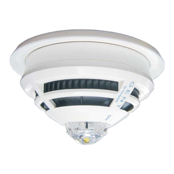
These instructions are for the S-Quad product range in white and black moulding. An S-Quad product integrates dual angle
smoke, heat and carbon monoxide gas detection with electronic sounder, speech and LED flasher (Visual Alarm Device - VAD)
in one assembly.
Technical Data
Operating voltage
Weight
Dimensions
IP rating
Enclosure
Colour
White
Black
Approval
Storage Temperature
Ambient operating temperature -10°C to +50°C
Relative Humidity
Heat (H)
Optical (O)
2
Dual Optical (O
)
Sounder (S)
Visual Alarm Device (VAD)
EN54-18 : 2005 - Input/Output devices
EN54-17 : 2005
- Short circuit isolator
(section 4.8) data
4188-1073 issue 3_2-17_P1_S-Quad
35V - 48V
Sensor head only 110g
(with Standard base - 170g)
(Standard Base with IP21 plate 230g)
Sensor head:
117mm diameter by 49.6mm height (With
base the height increases to 63.8mm)
(With base and IP 21 Plate - 140mm diameter
by 52mm height)
IP21C when Base is mounted on an IP21 plate
ABS
RAL 9010
Black (as material colour ABS HF380 Black)
LPCB approved
-20°C to +70°C
(for S-Quad with CO it is -20°C to +50°C)
95% non condensing (+5°C to +45°C)
EN54-5 : 2000, A1:2002
EN54-7 : 2000, A1:2002, A2:2006 ~
EN54-7 : 2000, A1:2002, A2:2006 ~
EN54-3 : 2001, A1:2002, A2:2006 ~
~ A2-2006 is not applicable for
S4-720,S4-715, S4-710 and S4-711
EN54-23 : 2010
Vmax
48V
I
C max
V
40V
I
nom
S max
V
24V
I
min
L max
V
12V
Z
so max
c max
V
so min
8V
042xx/xx
All LPCB approved Sensor STATES are listed in the
S-Quad Description and commissioning information.
Information on minimum sound output levels
to include polar dispersion is covered in a
technical note TECH7018.033, available on
request from manufacturer.
See section headed 'S-Quad (S4) Coverage'
in part 2 of this document for data on Visual
Alarm Devices coverage.
Symbols on product
0.8A
1.25A
4mA
0.112W
042bw/01
042bu/05
042bv/01
042ca/01
042bu/06
042ca/03
042bu/04
042ca/02
042bw/02
042ak/04
042bw/03
042bz/01
042bu/07
042bf/03
042bu/09
042ca/04
042bv/02
042bu/10
042bd/01
042bf/01
042bf/02
042be/01
042ak/01
Protective Earth connection
terminal.
The WEEE symbol. It indicates
the product is to be recycled and
not thrown away.
The CE compliance logo. This
product is in conformity with the
relevant European Union
harmonisation legislation.
The RoHS compliance logo. The
RoHS directive restricts the use
of certain hazardous substances
commonly used in electronic and
electronic equipment.
1
Advertisement

Subscribe to Our Youtube Channel
Related Manuals for Honeywell S-Quad


Summary of Contents for Honeywell S-Quad
- Page 1 Sensor, Sounder, Speech & Visual Alarm These instructions are for the S-Quad product range in white and black moulding. An S-Quad product integrates dual angle smoke, heat and carbon monoxide gas detection with electronic sounder, speech and LED flasher (Visual Alarm Device - VAD) in one assembly.
-
Page 2: Product Range
S4-700 Base (for all S4 Sensors) S4-705 IP21 Plate (5 pack) S4-701 IP21 Base (includes IP21 Plate) S4BK-700 Black Base for Black S-Quad S4BK-705 Black IP21 plate (5 per pack) 805589 Sensor dust cover (50 pack) 805580 Removal tool kit... - Page 3 Siting A S-Quad device plugs into a dedicated Base that is installed in the protected premises. The Bases should be sited in locations as defined by the project plans and by BS5839 : Part 1 : 2002 and VAD coverage defined in EN54 Part 23 .
- Page 4 Programmable input/output All S-Quad devices can be configured as either monitored input or unmonitored output. The factory setting of the programmable input / output is unmonitored output, to drive an external repeat LED without a series resistor. There is a maximum cable length limit of 15 metres from the S-Quad base to the external I/O Unit.
- Page 5 Place the dust cover onto the tool inside the cradle. Offer the An extractor tool allows removal and fitting of the S-Quad device cover to the S-Quad, locate and push to fit it onto the assembly. head into the base. By fitting a screw-on adaptor, the tool can be Withdraw the tool when the dust cover is in place.
- Page 6 Semi Flush fixing is only applicable for White body S-Quad range An S-Quad device in white device (non VAD/Sounder) can be semi-flush mounted to a ceiling tile to an approximate depth of 20mm, which is slightly deeper than the base assembly. To semi-flush mount a special housing must be used, which consists of a main assembly and a trim ring.
- Page 7 White - with Speech and/or Sounder Indicators Insect mesh The S-Quad has a red LED that gives an indication in assembly the event of a fire. The LED can be configured to flash Sensor periodically, as an 'in operation' confirmation, this indication is given system-wide at all S-Quads.
- Page 8 Dual Optical Sensor A piezo disk within the S-Quad assembly outputs the sound via a The optical sensing is performed by the dual angle optical horn, which is constructed in the chamber moulding. The volume...
- Page 9 The Visual Alarm Device (VAD) utilises a high-power red / white Attention tone Speech Message LED that receives its power from a super capacitor in the S-Quad Standard assembly. The high light output from the LED is made possible or Complex Message n by the low impedance of the capacitor.
- Page 10 'x' allows more flexibility, being specified between 3m and 6m. " All S-Quad VADs have a defined 'C' Category for each power setting and an 'O' category to allow it to meet the needs of building applications. Example An O-5-14 could be mounted at 5m and have a square spacing of 10m.
- Page 11 S-Quad Description & Commissioning S-Quad (S4) Visual Alarm Coverage High performance data of S-Quad White VAD (HPW) Power Maximum Maximum Maximum EN54-23 coverage and Additional EN54-23 setting loop loop total loop volume in cubic metres Category 'O' coverage current current...
- Page 12 Description & Commissioning S-Quad High performance of S-Quad Red VAD (HPR) Power Maximum Maximum Maximum EN54-23 coverage and Additional EN54-23 setting loop loop total loop volume in cubic metres Category 'O' coverage current current current and volume in cubic and power...
- Page 13 Example 1: A S-Quad VAD is used in an open area with a rating of O-5-14. The location has an ambient light level of up to 480 Lux and it can be viewed directly. The sensor is a Optical-CO-Heat. The maximum mounting height is: 5 x 1.1 = 5.5m...
- Page 14 Compatibility At the time of releasing this issue of data sheet the S-Quad devices were compatible for installation on the loop circuits of fire alarm system based on panels having the following Main Controller Card/Board (MCC / MCB) and Loop Processor Card (LPC) software.
- Page 15 S-Quad STATES The STATE in which an S-Quad sensor operate can be changed from the default factory set STATE to another STATE configured during commissioning using the Vigilon Commissioning tool. The environment in which an S-Quad device is installed will determine what STATE is used.
- Page 16 Medium sensitivity delayed optical smoke ³ Low sensitivity optical smoke sensing is not approved but may still be useful in certain applications. # - factory default settings S-Quad Dual Optical Heat & Optical Heat sensor STATES Sensitivity STATE Definition / Class...
- Page 17 STATE 6 which is only approved to EN54-5. ³ Low sensitivity optical smoke sensing is not approved but may still be useful in certain applications. The STATE 15 is no detection and is not part of LPCB approval. S-Quad Heat sensor STATES Sensitivity STATE Definition / Class...
- Page 18 S-Quad Status How to view S-Quad device Status To view the status of an S-Quad device following the allocation of the loop circuit on which it is installed Press Menu On/Off button. Select [Info], momentarily press <etc> to select [Status] Select [Device] and enter a device number Select [Loop] and enter the loop number and then [Enter] to view device status information.
- Page 19 S-Quad Description & Commissioning S-Quad Exceptions or Condition codes The Exception codes are also sometimes called condition codes and these codes provide information about a sensor device. A code indicates small changes in the: ¨ environmental condition ¨ sensor mechanism and ¨...
- Page 20 Description & Commissioning S-Quad How to interpret Exception Codes Exceptions Meaning Action /Condition codes This is the sub-fire band and if set should be No action need be taken. 1 0 0 0 0 0 0 0 0 0 or...
- Page 21 S-Quad Description & Commissioning Exception (or Condition) Codes for S-Quad devices Exception codes normal sub fault band fault band band type Description Optical None Small signal Subfire subfire sensed [Check [Check location, location, STATE & type] STATE & type] Heat subfire...
- Page 22 Description & Commissioning S-Quad S-Quad Time average reading The typical time average values for sensors under normal operating condition are shown in the table below. Part No Product Analogue Channels Time average Tnew S4-720 Heat Sensor 2 - heat S4-715...
- Page 23 S-Quad Description & Commissioning S-Quad - Message Action List This list shows the messages that are likely to be displayed at the control panel or at a loop repeat panel in the fire system. Message Action list The messages displayed at the control panel or loop repeat panels are given for guidance only: ¨...
- Page 24 S-Quad, if configured during commissioning, the S-Quad will output turbo and/or non turbo tones. The high and low FAB mappings are used to change the tone output of the S-Quad sounder. The turbo mode outputs a waveform with a basic frequency that is the same frequency as the resonant frequency of the S-Quad piezo.
-
Page 25: System Test
S-Quad Description & Commissioning System test Preparation ¨ Check to ensure access will be provided to areas where installed equipment is to be tested, such as in locked or secure areas. ¨ Ensure all sensor dust covers are removed. ¨... - Page 26 The 'artificial smoke' particles from smoke canister look more like steam. When the panel is in Test mode all the dual optical S-Quad sensors in the system are treated as single channel optical sensors. A single channel optical sensor overrides the false alarm immunity of dual optical sensor and permit the testing of the S-Quad sensors by using canned smoke.
- Page 27 - Low their resonant frequency. Background monitoring on New device / Old device (A new device can be an S-Cubed Mark 3 or an S-Quad Mark 2/3) No tick - Off, Grey tick...
- Page 28 Do not burn. Gent by Honeywell reserves the right to revise this publication from time to time and make changes to the content hereof without obligation to notify any person of such revisions of changes.
Need help?
Do you have a question about the S-Quad and is the answer not in the manual?
Questions and answers