
Related Manuals for SMA SUNNY BOY 8000TL-US


Summary of Contents for SMA SUNNY BOY 8000TL-US
- Page 1 PV Inverter SUNNY BOY 8000TL-US / 9000TL-US / 10000TL-US Installation Guide SB8-10TL-IUS103811 | IMUS-SB8-10TLUS | Version 1.1...
- Page 3 (with no limitation) any implied warranties of utility, merchantability, or fitness for any particular purpose. All such warranties are expressly disclaimed. Neither SMA America, LLC nor its distributors or dealers shall be liable for any indirect, incidental, or consequential damages under any circumstances.
- Page 4 A warning describes a hazard to equipment or personnel. It calls attention to a procedure or practice, which, if not correctly performed or adhered to, could result in damage to or destruction of part or all of the SMA equipment and/or other equipment connected to the SMA equipment or personal injury. DANGER DANGER indicates a hazardous situation which, if not avoided, will result in death or serious injury.
- Page 5 SMA America, LLC Important Safety Instructions Other symbols in this document In addition to the safety and hazard symbols described on the previous pages, the following symbol is also used in this installation manual: Information This symbol accompanies notes that call attention to supplementary information that you must know and use to ensure optimal operation of the system.
- Page 6 The Sunny Boy contains no user-serviceable parts except for the fans on the bottom of the enclosure and the filters behind the fans as well as the handle covers on the sides of the unit. For all repair and maintenance, always return the unit to an authorized SMA Service Center.
-
Page 7: Table Of Contents
Mounting the wall mounting bracket....... 23 Mounting the SMA DC Disconnect..... . 25 Mounting the Sunny Boy onto the wall mounting bracket . - Page 8 Opening SMA DC Disconnect ......50 Closing SMA DC Disconnect ......51 Maintenance.
- Page 9 Technical data........60 12.1 Sunny Boy 8000TL-US ....... 60 12.2 Sunny Boy 9000TL-US .
- Page 10 Table of Contents SMA America, LLC SB8-10TL-IUS103811 Installation Guide...
-
Page 11: Notes On This Manual
You will find further information on special topics in the download area at www.SMA-America.com. 1.5 Nomenclature In this document SMA America Production, LLC is referred to in the following as SMA. The syntax specified here for menus and parameters applies throughout the entire manual:... -
Page 12: Safety
Separate the Sunny Boy securely from the grid and the PV generators using AC and DC disconnectors. You must provide an AC circuit breaker. The SMA DC Disconnect is included in the delivery of the Sunny Boy and must be used for operating the inverter. - Page 13 690.35 string fuses are required to protect the installation from reverse currents. String fuses can be installed in the SMA Sunny Boy Combiner Box. Refer to the appropriate manual for detail information. You can get more information about the Sunny Boy Combiner Box at www.SMA-America.com.
-
Page 14: Safety Instructions
When designing the PV plant, ensure that the values comply with the permitted operating range of all components at all times. The free design programs "Solar Design Tools" (www.SMA-America.com) will assist you. The manufacturer of the PV modules must have approved the modules for use with this Sunny Boy device. -
Page 15: The Sunny Boy
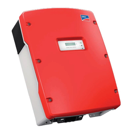
SMA America, LLC The Sunny Boy 3 The Sunny Boy 3.1 Parts of the Sunny Boy Position Description Ergonomic handles Display Fans 3.2 Position of the Labels Position Description Type label General warning label Warning label DC connection Installation Guide SB8-10TL-IUS103811... -
Page 16: Identifying The Sunny Boy
The Sunny Boy SMA America, LLC 3.3 Identifying the Sunny Boy You can identify the Sunny Boy by the type label. It is on the right side of the enclosure. The type label shows: • The serial number (Serial No.). • The type of product (Type/Model). -
Page 17: Unpacking And Inspection
Screws and washers for fastening the DC Disconnect to the wall-mounting bracket If not ordered differently, the SMA Sunny Boy Combiner Box is included in the scope of delivery as a standard feature. Refer to the appropiate manual for detail information. -
Page 18: Mounting
Mounting SMA America, LLC 5 Mounting 5.1 Safety DANGER Danger to life due to fire or explosions. There is always a certain risk with electric devices that a fire can occur, even though greatest attention was paid to avoiding this during the development. -
Page 19: Selecting The Mounting Location
SMA America, LLC Mounting 5.2 Selecting the mounting location Observe the following conditions during installation: • The installation method and mounting location must be suitable for the weight and dimensions of the Sunny Boy (see section 12 ”Technical data” (page 60)). • Take the dimensions of the DC Disconnect into account (Page 25). -
Page 20: Mounting The Sunny Boy With The Wall Mounting Bracket
Mounting SMA America, LLC • Observe the minimum clearances to walls, other devices or objects as shown in the diagram in order to guarantee sufficient heat dissipation. Position Clearance Above 12 in. (30 cm) Below 36 in. (90 cm) Left 12 in. - Page 21 SMA America, LLC Mounting Dimensions of the wall mounting bracket Installation Guide SB8-10TL-IUS103811...
-
Page 22: Possibilities For Mounting The Wall Mounting Bracket
Mounting SMA America, LLC 5.3.1 Possibilities for mounting the wall mounting bracket Mounting on stone wall Attach the wall mounting bracket with a minimum of 3 screws. The position of the screws on the wall mounting bracket is as follows: • 1 screw on the upper left side. -
Page 23: Mounting The Wall Mounting Bracket
SMA America, LLC Mounting 5.3.2 Mounting the wall mounting bracket 1. Position the wall-mounting bracket against the wall where you intend to mount the Sunny Boy. Try to mount the Sunny Boy with the display at eye-level. 2. Place a level on the top edge of the bracket. Adjust the position until it is leveled. The bottom of the bracket will be the approximate location of the bottom of the inverter. - Page 24 Mounting SMA America, LLC Tip for installing The diameter of the holes you drill must match the hardware you are using to mount the Sunny Boy. For example, if you are mounting the Sunny Boy to a concrete wall, the hole diameter should be approximately the same as the outside diameter of the concrete anchors you intend to use.
-
Page 25: Mounting The Sma Dc Disconnect
5.4 Mounting the SMA DC Disconnect Dimensions of the SMA DC Disconnect Attach the SMA DC Disconnect to the two lower holes of the wall-mounting bracket, using two screws and washers provided. 1. Place the screws and the washers in the holes in the fastening tabs on the DC Disconnect. -
Page 26: Mounting The Sunny Boy Onto The Wall Mounting Bracket
The air grills are marked "rechts/right" and "links/left" on the interior for proper assignment. The air grills prevent dirt and insects from entering the device and if necessary, can be reordered from SMA America 13 ”Accessories” (page 70). ☑ The Sunny Boy is mounted. SB8-10TL-IUS103811 Installation Guide... -
Page 27: Electrical Connection
SMA America, LLC Electrical Connection 6 Electrical Connection 6.1 Safety NOTICE Ingress of water when mounting and installing the Sunny Boy. Damage to the Sunny Boy will result. • Do not open the Sunny Boy when it is raining or when high humidity is present (> 95 %). -
Page 28: Wiring Diagram With Sma Dc Disconnect And Combiner Box
Electrical Connection SMA America, LLC 6.2 Wiring Diagram with SMA DC Disconnect and Combiner Box For operating the Sunny Boy the provided SMA DC Disconnect must be used. SB8-10TL-IUS103811 Installation Guide... -
Page 29: Insert The Cable Into The Sma Dc Disconnect
5. Turn off the main switch in the switch cabinet. 6. Cover the PV modules with opaque material. 7. Pull the AC and DC cables through the cable conduits into the SMA DC Disconnect. ☑ The cables are inserted into the SMA DC Disconnect. -
Page 30: Sunny Boy Connection Area Overview
Electrical Connection SMA America, LLC 6.4 Sunny Boy connection area overview In the following overview illustration there is a schematic representation of the connection area of an open Sunny Boy with SMA DC Disconnect. SB8-10TL-IUS103811 Installation Guide... -
Page 31: Ac Connection
Sunny Boy: Ground terminal (PE) Sunny Boy: Output AC line terminals (N, L1 and L2) Varistor terminal with varistors SMA DC Disconnect: Output AC line terminals (N, L1 and L2) SMA DC Disconnect: Grounding electrode terminal for the connection of: • Grounding electrode conductor •... -
Page 32: Ac Cable Requirements
SMA America, LLC 6.5.1 AC cable requirements Cable sizing Use the free design programs "Solar Design Tools" at www.SMA-America.com to determine the correct string configuration. Connection requirements of the utility operator Always observe the connection requirements of your grid operator. - Page 33 SMA America, LLC Electrical Connection Load disconnection unit You must install a separate line circuit breaker for each inverter in order to ensure that the inverter can be securely disconnected under load. See the technical data for the maximal permissible rating Page 60).
-
Page 34: Connect The Ac Cable In The Dc Disconnect
8. Place the cover back onto the fuse box. 9. Tighten the screws. 10. Open the DC Disconnect as described in section 8.3 ”Opening SMA DC Disconnect” (page 50). 11. Lead the AC cable through the cable conduit from the inside of the fuse box into the inside of the DC Disconnect. -
Page 35: Connecting The Ac Cable In The Sunny Boy
16. Connect the N (AC line N) wire to the terminal labeled N in the SMA DC Disconnect. 17. Connect the wires to the terminal blocks in the SMA DC Disconnect and tighten to a torque of 40 in‑lbs. (4.5 Nm). 18. Verify that all connections are correctly wired and properly torqued. Pull on the cable in order to make sure that it is sufficiently fixed in the terminal. - Page 36 9. Verify that all connections are correctly wired and properly torqued. Pull on the cable in order to make sure that it is sufficiently fixed in the terminal. 10. Close the SMA DC Disconnect as described in section 8.4 ”Closing SMA DC Disconnect” (page 51).
-
Page 37: Dc Connection
SMA America, LLC Electrical Connection 6.6 DC connection This section provides procedures for wiring the DC input from the PV array to the Sunny Boy. Simplified electrical wiring diagram of a PV system WARNING Danger of fire due to overheating. • Fuse all DC+ und DC − wires of the strings connected to the DC Disconnect. -
Page 38: Dc Connection Requirements
2. Follow all safety instructions of the PV module manufacturer. 3. Open the SMA DC Disconnect as described in section 8.3 ”Opening SMA DC Disconnect” (page 50). 4. Lead the AC cable through the cable conduit into the inside of the SMA DC Disconnect. SB8-10TL-IUS103811 Installation Guide... - Page 39 + in the SMA DC Disconnect. 14. Torque all wires in the terminal blocks inside the SMA DC Disconnect to 40 in-lbs. (4.5 Nm). 15. Verify that all connections are correctly wired and properly torqued. Pull on the cable in order to make sure that it is sufficiently fixed in the terminal.
- Page 40 23. Verify that all connections are correctly wired and properly torqued. Pull on the cable in order to make sure that it is sufficiently fixed in the terminal. 24. Close the SMA DC Disconnect as described in section 8.4 ”Closing SMA DC Disconnect” (page 51).
-
Page 41: Communication
(page 30)) to communicate with special data acquisition devices (e.g. Sunny WebBox) or a PC with appropriate software (e.g. Sunny Data). For a complete listing of all applicable communication options refer to the SMA web page or the product catalogue. -
Page 42: Commissioning
2. Connect the grid voltage to the Sunny Boy by switching on the main AC circuit breaker in the main utility panel. 3. Switch the SMA DC Disconnect to position labeled as ”1”. If there is sufficient sunlight available, the Sunny Boy will enter the “Wait” mode at this time and the green LED will begin to blink. -
Page 43: Display
SMA America, LLC Commissioning 7.1 Display Feeding operation After fault-free grid connection of the Sunny Boy it takes approximately one minute until the following display messages are shown alternately. The display messages shown before only have the purpose of indicating the initialization of the Sunny Boy and the process of controlling whether the power supply requirements are fulfilled. - Page 44 • Greater than 600 V: Contact the planner/installer of the PV generator for assistance. • Lower than 600 V: Reconnect the Sunny Boy to the PV generator as described in section 6.6 ”DC connection” (page 37). • If the message occurs again, disconnect the Sunny boy again and contact SMA (see section 14 ”Contact” (page 71)). SB8-10TL-IUS103811...
-
Page 45: Led Display
SMA America, LLC Commissioning 7.2 LED Display Overview Green Yellow Status Glows continuously Does not glow Does not glow OK (feeding operation) Glows continuously Does not glow Disturbance Glows continuously OK (initialization) Flashes quickly Does not glow Does not glow OK (stop) - Page 46 Commissioning SMA America, LLC Feeding operation After a fault-free grid connection of the Sunny Boy, it takes approximately one minute until the green LED is continuously on. The blink codes shown before only have the purpose of indicating the initialization of the Sunny Boy and the process of checking whether the power supply requirements are fulfilled.
-
Page 47: Setting The Display Language
• Lower than 600 V: Reconnect the Sunny Boy to the PV generator as described in section 6.6 ”DC connection” (page 37). If the message occurs again, disconnect the Sunny boy again and contact SMA America (see section 14 ”Contact” (page 71)). 7.3 Setting the display language You can set the language of the display using the switches on the underside of the display assemblies inside the Sunny Boy. -
Page 48: Opening And Closing
Opening and closing SMA America, LLC 8 Opening and closing NOTICE Electrostatic discharges. Internal components of the Sunny Boy can be irreparably damaged by electrostatic discharge. • Ground yourself before you touch a component. 8.1 Opening the Sunny Boy DANGER During operation, high voltages are present in the Sunny Boy. -
Page 49: Closing The Sunny Boy
SMA America, LLC Opening and closing 8.2 Closing the Sunny Boy 1. Check wire routing to ensure that no wires can interfere with proper sealing of the lid and that no pressure will be exerted on the connections when the lid is replaced. -
Page 50: Opening Sma Dc Disconnect
8.3 Opening SMA DC Disconnect 1. Turn the SMA DC Disconnect off by turning the switch to ”0” (A). 2. Loosen the screw in the right area of the SMA DC Disconnect (B) using a small phillips screwdriver (used screw: UNC no 5 x ⁄... -
Page 51: Closing Sma Dc Disconnect
in. cross recess Phillips pan head machine screw). 4. Install the screw and washer at the bottom side of the SMA DC Disconnect (C), to fasten the lid. The teeth of the washer must face toward the lid in order to ensure proper grounding. Tighten the screw to a torque of 44 in‑lbs. -
Page 52: Maintenance
Maintenance SMA America, LLC 9 Maintenance 9.1 Checking heat dissipation 9.1.1 Cleaning the fans If the fan guards are only dirtied with loose dust, they can be cleaned with a vacuum cleaner. If you do not achieve satisfactory results with a vacuum cleaner, dismantle the fan for cleaning. -
Page 53: Cleaning The Handle Covers
SMA America, LLC Maintenance 9.1.2 Cleaning the handle covers The Sunny Boy sucks air in from underneath via the fans and blows it out again at the top on both sides via the handle covers. Clean the handle covers, if they are dirty. Proceed as follows: 1. -
Page 54: Checking The Fans
Sunny Boy accessories kit). Setting the parameter 1. Request the installer password on the SMA Serviceline (contact: see Page 71). 2. Set the "Fan Test" parameter to ”1” in the installer mode. 3. Check the fans air-flow. -
Page 55: Troubleshooting
Do not attempt to carry out repairs other than those described here. Instead, use the SMA replacement and repair services. You can find more information on the replacement and repair services in the warranty conditions included with the Sunny Boy. - Page 56 Troubleshooting SMA America, LLC NOTICE Excessive voltages can destroy the measuring device. • Only use measuring devices with a DC input voltage range up to at least 600 V. 2. Measure the voltages between the plus and minus pole of a string against the ground potential.
-
Page 57: Inspecting And Changing The Varistors
3.5 mm screwdriver. 4. Remove the varistor (2). 5. Insert a new varistor (3). 6. Close the DC Disconnect as described in section 8.4 ”Closing SMA DC Disconnect” (page 51). ☑ The check and replacement of the varistors is completed. Installation Guide... -
Page 58: Decommissioning
2. Remove all connector cables from the Sunny Boy. 3. Close the Sunny Boy with the six screws and the corresponding washers. 4. Open the SMA DC Disconnect as described in section 8.3 ”Opening SMA DC Disconnect” (page 50). 5. Open the terminals and remove all cables from the SMA DC Disconnect. -
Page 59: Packaging
− 13 °F ... +140 °F ( − 25 °C ... +60 °C). 11.4 Disposal Dispose the Sunny Boy and SMA DC Disconnect at the end of its service life in accordance with the disposal regulations for electronic scrap which apply at the installation site at that time. Alternatively, send it back to SMA with shipping paid by sender, and labeled "FOR DISPOSAL"... -
Page 60: Technical Data
Technical data SMA America, LLC 12 Technical data Specifications subject to change without notice. Values at nominal conditions. 12.1 Sunny Boy 8000TL-US PV generator connection data Maximum DC power 8,300 W Maximum array input power (DC@STC) 10,000 W Maximum DC voltage 600 V Peak power track voltage 300 V ... - Page 61 (width x height x depth) 467 mm x 838 mm x 241 mm Weight of the inverter 77 lbs. (35 kg) Weight of the SMA DC disconnect 8 lbs. (3.5 kg) Ambient temperature range − 13 °F ... +140 °F ( − 25 °C ... +60 °C) Ambient temperature range (full power output) −...
-
Page 62: Sunny Boy 9000Tl-Us
Technical data SMA America, LLC 12.2 Sunny Boy 9000TL-US PV generator connection data Maximum DC power 9,300 W Maximum array input power (DC@STC) 11,250 W Maximum DC voltage 600 V Peak power track voltage 300 V ... 480 V Maximum DC input current... - Page 63 (width x height x depth) 467 mm x 838 mm x 241 mm Weight of the inverter 77 lbs. (35 kg) Weight of the SMA DC disconnect 8 lbs. (3.5 kg) Ambient temperature range − 13 °F ... +140 °F ( − 25 °C ... +60°C) Ambient temperature range (full power output) −...
-
Page 64: Sunny Boy 10000Tl-Us
Technical data SMA America, LLC 12.3 Sunny Boy 10000TL-US PV generator connection data Maximum DC power 10,350 W Maximum array input power (DC@STC) 12,500 W Maximum DC voltage 600 V Peak power track voltage 300 V ... 480 V Maximum DC input current... - Page 65 (width x height x depth) 467 mm x 838 mm x 241 mm Weight of the inverter 77 lbs. (35 kg) Weight of the SMA DC disconnect 8 lbs. (3.5 kg) Ambient temperature range − 13 °F ... +140 °F ( − 25 °C ... +60 °C) Ambient temperature range (full power output) −...
-
Page 66: Sma Dc Disconnect
Technical data SMA America, LLC 12.4 SMA DC Disconnect PV generator connection data Maximum DC voltage 600 V Operating DC voltage range 0 V ... 600 V Maximum DC operating current 35 A Maximum DC short circuit current 45 A Maximum String Fuse Rating... -
Page 67: Fcc Compliance Information
• Connect the equipment into an outlet on a circuit different from that to which the receiver is connected. • Consult the dealer or an experienced radio/TV technician for help. • The user is cautioned that changes or modifications not expressly approved by SMA America, Inc. could void the user’s authority to operate this equipment. Installation Guide... -
Page 68: Trip Limits/Trip Times
Technical data SMA America, LLC 12.6 Trip limits/trip times Nominal Trip limit Trip frequencies Trip times frequency 60 Hz > 60.5 Hz 60.45 Hz ... 60.55 Hz max. 0.1602 s < 57.0 Hz ... 59.8 Hz 56.95 Hz ... 59.85 Hz adjustable 0.16 s ... 300 s (default 59.3 Hz) (default 59.25 Hz ... -
Page 69: Torque Values And Wire Sizes
DC Disconnect lid Lid screws 13 Accessories You will find the corresponding accessories and replacement parts for your product in the following overview. If needed, you can order these from SMA or your SMA dealer. Name Description SMA order number... -
Page 70: Contact
Contact SMA America, LLC 14 Contact If you have technical problems concerning our products, contact your installer or the SMA Serviceline. We require the following information in order to provide you with the necessary assistance: • Inverter type • Type and number of modules connected •...
Need help?
Do you have a question about the SUNNY BOY 8000TL-US and is the answer not in the manual?
Questions and answers