Advertisement
Quick Links
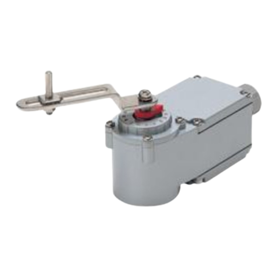
INSTRUCTION MANUAL
2-WIRE POSITION TRANSMITTER
(linear motion type; 45-degree rotation)
BEFORE USE ....
Thank you for choosing M-System. Before use, please check
contents of the package you received as outlined below.
If you have any problems or questions with the product,
please contact M-System's Sales Office or representatives.
■ PACKAGE INCLUDES:
VOS2T unit ..........................................................................(1)
Cable, approx. 1 meter long (optional) ...............................(1)
Cable connector (optional) ..................................................(1)
Lever assembly
Lever ........................................................................(1)
Connecting pin ........................................................(1)
Nailed nut ................................................................(1)
Nut with washer (M5) .............................................(1)
Screws for attaching the lever (M5 × 8) .............................(1)
Plain washer (M5) ...............................................................(1)
Toothed washer (M5, external teeth) .................................(1)
Note: Bracket and other components necessary to attach the
VOS2T to an actuator are to be provided by the cus-
tomer.
Clamp Set (model: VOCP) is available to simplify the
connection.
■ MODEL NO.
Confirm Model No. marking on the product to be exactly
what you ordered.
5-2-55, Minamitsumori, Nishinari-ku, Osaka 557-0063 JAPAN
Phone: +81(6)6659-8201 Fax: +81(6)6659-8510 E-mail: info@m-system.co.jp
MODEL
POINTS OF CAUTION
■ CONFORMITY WITH EU DIRECTIVES
• When the unit is mounted onto a grounded metal bracket,
insert a noise filter for the output. COSEL Noise Filter
Model NAC-04-472 or equivalent is recommended.
■ GENERAL PRECAUTION
• Cut power supply to the unit before wiring to it.
■ ENVIRONMENT
• Inside building. If outside, keep away from direct sun-
light.
• Operating temperature -5 to +60°C (23 to 140°F)
• Operating humidity 30 to 90% RH
■ DESIGN OF MOUNTING BRACKET
• The size 'x' indicated in Figure 2 must be longer than 10%
of full-stroke of the actuator when it is in the middle po-
sition.
• The VOS2T unit must be positioned in parallel or in ver-
tical to the actuator stroke.
■ ACTUATOR SIDE LEVER
• When the actuator side lever is provided by the customer,
be sure that width of the hole threading the connecting
pin is 5 millimeters or wider. Diameter of connecting pin:
5
mm
0
–0.03
■ GASKET
• Be sure to return the gasket when you close the unit cover
after wiring or adjustments.
■ TORQUE
• For the screws attached to the cover, tightening torque is
between 1.2 and 1.6 N·m.
VOS2T
EM-4767 Rev.2 P. 1 / 4
Advertisement

Related Manuals for M-system VOS2T


Summary of Contents for M-system VOS2T
- Page 1 Note: Bracket and other components necessary to attach the • The VOS2T unit must be positioned in parallel or in ver- VOS2T to an actuator are to be provided by the cus- tical to the actuator stroke.
- Page 2 As you see in Figure 3, the output signal of the VOS2T is proportional to the sine q of the lever angle. Position of the connecting pin is determined by the following equation.
- Page 3 (seen from the lever side). is approximately 12mA with 50% actuator position (θ = 0° in Figure 3), and where the VOS2T side lever and the actua- ■ HOW TO ADJUST ZERO AND SPAN tor side lever are positioned in a straight line. See Figure 4 1) If you need reverse action, change the setting now.
- Page 4 (e.g. connecting pin position) • If the VOS2T is installed outside the building or where it is subject to water or metallic dust particles, check that there is no crack or bruise on the gasket. If you find any, consult M-System or local representative.
Need help?
Do you have a question about the VOS2T and is the answer not in the manual?
Questions and answers