Table of Contents
Advertisement
Quick Links
Space-saving Dual Output Signal Conditioners
Mini-MW Series
RTD TRANSMITTER
(PC programmable)
Functions & Features
• Accepts direct input from a RTD
• 4-wire connection available
• Two independent output ranges
• Linearization and burnout
• PC programmable
• High-density mounting
Typical Applications
• Long distance transmission between the RTD
and the transmitter
• Combination with intrinsic safety barriers
29.5 (1.16)
89
(3.51)
124
(4.88)
mm (inch)
MODEL: W2XR–[1][2][3]-[4][5]
ORDERING INFORMATION
• Code number: W2XR-[1][2][3]-[4][5]
Specify a code from below for each [1] through [5].
(e.g. W2XR-4Z1V3-M2/N/Q)
• Temperature range (e.g. 0 – 100 °C)
• Output 1 range (e.g. 4 – 20 mA DC)
• Output 2 range (e.g. 1 – 5 V DC)
• Specify the specification for option code 'Q.'
(e.g. /C01/S01)
Note: If one of the outputs should be a current range,
specify it for the Output 1 to allow a greater load.
[1] INPUT RTD
1: JPt 100 (JIS'89)
(Usable range: -200 to +500°C, -328 to +932°F; min.span: 20°C, 36°F)
3: Pt 100 (JIS'89)
(Usable range: -200 to +650°C, -328 to +1202°F; min.span: 20°C, 36°F)
SEN TRONIC
AG
Produkte, Support und Service
4: Pt 100 (JIS'97, IEC)
(Usable range: -200 to +850°C, -328 to +1562°F; min.span: 20°C, 36°F)
5: Pt 50 Ω (JIS'81)
(Usable range: -200 to +649°C, -328 to +1200°F; min.span: 20°C, 36°F)
7: Pt 1000
(Usable range: -200 to +850°C, -328 to +1562°F; min.span: 20°C, 36°F)
9: Cu 10 @25°C
(Usable range: -50 to +250°C, -58 to +482°F; min.span: 20°C, 36°F)
0: Specify (Please provide a resistance table.)
(Configurator software is used to change the input type and
precise range.)
[2] OUTPUT 1
Current
Z1: Range 0 – 20 mA DC
Voltage
V2: Range -10 – +10 V DC
V3: Range -5 – +5 V DC
(Configurator software is used to change output over the
described range of the selected suffix code.
For changing between suffix codes, set the Output Range
Selector on the side of unit before software adjustment.)
[3] OUTPUT 2
Same range availability as Output 1
Y: None
(Configurator software is used to change output over the
described range of the selected suffix code.
For changing between suffix codes, set the Output Range
Selector on the side of unit before software adjustment.)
[4] POWER INPUT
AC Power
M2: 100 – 240 V AC (Operational voltage range 85 – 264 V,
47 – 66 Hz)
DC Power
R: 24 V DC
(Operational voltage range 24 V ±10 %, ripple 10 %p-p max.)
R2: 11 – 27 V DC
(Operational voltage range 11 – 27 V, ripple 10 %p-p max.)
P: 110 V DC
(Operational voltage range 85 – 150 V, ripple 10 %p-p max.)
[5] OPTIONS (multiple selections)
Standards & Approvlas (must be specified)
/N: Without CE
Other Options
blank: none
/Q: Option other than the above (specify the specification)
Rugghölzli 2
Tel. +41 (0)56 222 38 18
CH - 5453 Busslingen
Fax +41 (0)56 222 10 12
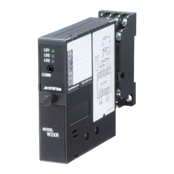
MODEL: W2XR
mailbox@sentronic.com
www.sentronic.com
Advertisement
Table of Contents

Related Manuals for M-system W2XR


Summary of Contents for M-system W2XR
- Page 1 [4] POWER INPUT ORDERING INFORMATION AC Power M2: 100 – 240 V AC (Operational voltage range 85 – 264 V, • Code number: W2XR-[1][2][3]-[4][5] 47 – 66 Hz) Specify a code from below for each [1] through [5]. DC Power (e.g.
-
Page 2: Related Products
SPECIFICATIONS OF OPTION: Q (multiple selections) maintained. COATING (For the detail, refer to M-System's web site.) Load resistance: Output drive 12 V max. for Output 1; 7 V /C01: Silicone coating max. for Output 2 /C02: Polyurethane coating (e.g. -
Page 3: External View
MODEL: W2XR CALCULATION EXAMPLES OF OVERALL ACCURACY [Example] Pt 100, 0 – 100°C, Output Type -5 – +5 V, Output Range 1 – 5 V Input Accuracy* (0.15°C* ) ÷ Span (100°C) × 100 % + Max. Output Range (10 V) ÷ Span (4 V) × 0.04 % = 0.25 % *2, Calculate the accuracy in °C. - Page 4 MODEL: W2XR SCHEMATIC CIRCUITRY & CONNECTION DIAGRAM STATUS 2.5V 2-wire 3-wire 4-wire DIP SW Isolation Digital Output Computation Driver OUTPUT 1 – Low Drift DIP SW Amplifier Output Driver OUTPUT 2 – 13kΩ U(+) CONFIGURATOR JACK POWER V(–) Base Socket Remark: The section enclosed by broken line is only with 2nd output option.
-
Page 5: Component Identification
• The unit is designed to function as soon as power is sup- plied, however, a warm up for 10 minutes is required for Thank you for choosing M-System. Before use, please check satisfying complete performance described in the data contents of the package you received as outlined below. -
Page 6: Terminal Connections
W2XR INSTALLATION TERMINAL CONNECTIONS Loosen the fixing screw at the front of the unit in order to Connect the unit as in the diagram below or refer to the con- separate the body from the base socket. nection diagram on the side of the unit. -
Page 7: Maintenance
When the output is out of tolerance, recalibrate the unit using the PC Configurator Software (model: W2CFG). LIGHTNING SURGE PROTECTION M-System offers a series of lightning surge protector for protection against induced lightning surges. Please contact M-System to choose appropriate models. SEN TRONIC Rugghölzli 2... -
Page 8: External Dimensions
M-System’s option, the repair, replacement or refund of the purchase price of any M-System product which is defective under the terms of this warranty. To submit a claim under this warranty, the purchaser must return, at its expense, the defective M-System product to the below address together with a copy of its original sales invoice.
Need help?
Do you have a question about the W2XR and is the answer not in the manual?
Questions and answers