Advertisement
Quick Links
INSTRUCTION MANUAL
2-WIRE POSITION TRANSMITTER
(rotary motion type; 90-degree rotation)
BEFORE USE ....
Thank you for choosing M-System. Before use, please check
contents of the package you received as outlined below.
If you have any problems or questions with the product,
please contact M-System's Sales Office or representatives.
■ PACKAGE INCLUDES:
VOS2T-R unit ......................................................................(1)
Cable, approx. 1 meter long (optional) ...............................(1)
Cable connector (optional) ..................................................(1)
Lever assembly
Lever ........................................................................(1)
Connecting pin ........................................................(1)
Nailed nut ................................................................(1)
Nut with washer (M5) .............................................(1)
Screws for attaching the lever (M5 × 8) .............................(1)
Plain washer (M5) ...............................................................(1)
Toothed washer (M5, external teeth) .................................(1)
Toothed washer (M5, internal teeth) ..................................(1)
Note: Bracket, link and other components necessary to attach
the VOS2T-R to an actuator are to be provided by the
customer.
Link Set (model: VOLK) is available to simplify the con-
nection.
■ MODEL NO.
Confirm Model No. marking on the product to be exactly
what you ordered.
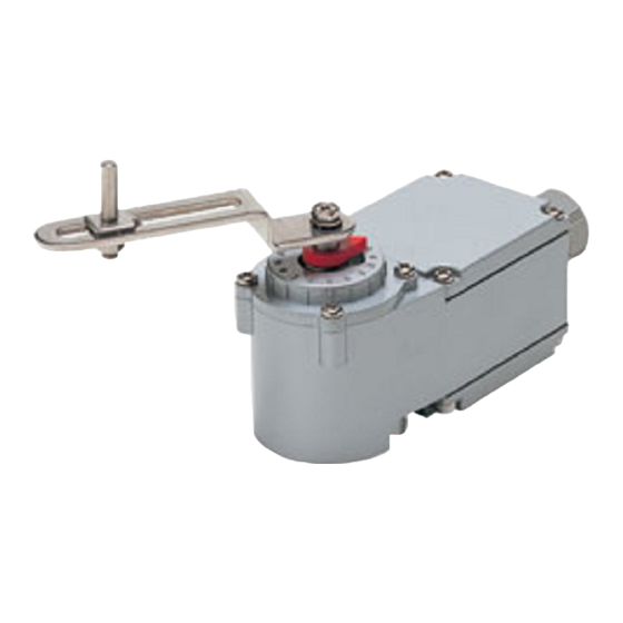
COMPONENT IDENTIFICATION
Cover
Body
Specifications
Screw for Lever
Zero Adjustment (Z)
Plain Washer
External Toothed Washer
Span Adjustment (S)
Lever
Internal Toothed Washer
Shaft
Indicator
Output Terminal (+)
Output Terminal (–)
Cable Connector
Cable
Figure 1
5-2-55, Minamitsumori, Nishinari-ku, Osaka 557-0063 JAPAN
Phone: +81(6)6659-8201 Fax: +81(6)6659-8510 E-mail: info@m-system.co.jp
MODEL
POINTS OF CAUTION
■ CONFORMITY WITH EU DIRECTIVES
• When the unit is mounted onto a grounded metal bracket,
insert a noise filter for the output. COSEL Noise Filter
Model NAC-04-472 or equivalent is recommended.
■ GENERAL PRECAUTION
• Cut power supply to the unit before wiring to it.
■ ENVIRONMENT
• Inside building. If outside, keep away from direct sun-
light.
• Operating temperature -5 to +60°C (23 to 140°F)
• Operating humidity 30 to 90% RH
■ ACTUATOR SIDE LEVER
• When the actuator side lever is provided by the customer,
be sure that diameter of the hole threading the connect-
ing pin is 5 millimeters or wider. Diameter of connecting
pin: 5
0
mm
–0.03
■ GASKET
• Be sure to return the gasket when you close the unit cover
after wiring or adjustments.
■ TORQUE
• For the screws attached to the cover, tightening torque is
between 1.2 and 1.6 N·m.
Upper side
Jumpers (JP1, JP2)
DIRECT
JP2
R
JP1
VOS2T-R
Lower side
REVERSE
JP2
D
R
D
JP1
EM-4766 Rev.6 P. 1 / 4
Advertisement

Related Manuals for M-system VOS2T-R


Summary of Contents for M-system VOS2T-R
- Page 1 5 millimeters or wider. Diameter of connecting pin: 5 –0.03 Note: Bracket, link and other components necessary to attach the VOS2T-R to an actuator are to be provided by the ■ GASKET customer. • Be sure to return the gasket when you close the unit cover Link Set (model: VOLK) is available to simplify the con- after wiring or adjustments.
- Page 2 Lever, VOS2T-R Side Figure 4 ■ LINKING WITHOUT LEVERS Refer to Figure 5 below when the VOS2T-R is to be connect- Actuator Stem ed directly to an actuator without utilizing levers. Adjust the relative positions of the actuator stem and VOS2T-R shaft so that their center positions are in a straight line, or otherwise use a coupling which can absorb position slides.
- Page 3 See Figure 9. INPUT % 2) For using levers to link, loosen the VOS2T-R side nut and washer and set the connecting pin (or bolt) position 6) With 100% input, adjust the relative to other components so that the distance A – B other half of the deviation Fig.
- Page 4 (e.g. connecting pin position) • If the VOS2T-R is installed outside the building or where it is subject to water or metallic dust particles, check that there is no crack or bruise on the gasket. If you find any, consult M-System or local representative.
Need help?
Do you have a question about the VOS2T-R and is the answer not in the manual?
Questions and answers