Table of Contents
Advertisement
Quick Links
INSTRUCTION MANUAL
CONFERENCE SYSTEM
TS-820 SERIES
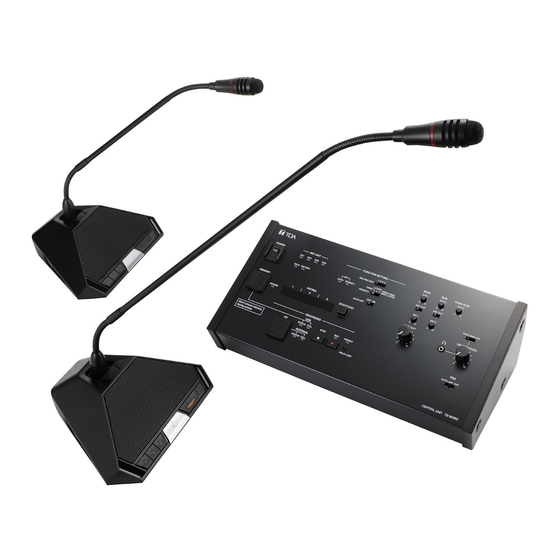
Infrared transmitter/receiver
Infrared delegate unit
Infrared chairman unit
Central unit
The figure shows the TS-820RC.
Thank you for purchasing TOA's Conference system.
Please carefully follow the instructions in this manual to ensure long, trouble-free use of your equipment.
Advertisement
Table of Contents


Need help?
Do you have a question about the TS-820 Series and is the answer not in the manual?
Questions and answers