Toa TS-910 Series Installation Manual
Hide thumbs
Also See for TS-910 Series:
- Operating instructions manual (44 pages) ,
- Instruction manual (52 pages)
Table of Contents
Advertisement
Quick Links
CONFERENCE SYSTEM
Infared Transmitter/
Receiver
Central unit
Expansion unit
Thank you for purchasing TOA's Conference System.
Please carefully follow the instructions in this manual to ensure long, trouble-free use of your equipment.
INSTALLATION MANUAL
TS-910 SERIES
E R
O N
P O W
O FF
SU
B
IN
MA
ES
PH
ON
HE
AD
Infrared Delegate unit
Wired Delegate unit
Bridge unit
(1-Conference unit
connection type)
E R
P O W
O N
O FF
SU
B
IN
MA
ES
PH
ON
HE
AD
Infrared Chairman unit
Wired Chairman unit
Bridge unit
(4-Conference unit
connection type)
Advertisement
Table of Contents

Related Manuals for Toa TS-910 Series


Summary of Contents for Toa TS-910 Series
- Page 1 Wired Chairman unit Central unit Bridge unit (1-Conference unit Bridge unit connection type) (4-Conference unit connection type) Expansion unit Thank you for purchasing TOA's Conference System. Please carefully follow the instructions in this manual to ensure long, trouble-free use of your equipment.
-
Page 2: Table Of Contents
TABLE OF CONTENTS 1. SAFETY PRECAUTIONS ................4 2. GENERAL DESCRIPTION ................6 3. SYSTEM EQUIPMENT CONFIGURATION ........7 4. NOMENCLATURE AND FUNCTIONS ..........8 4.1. Central Unit TS-910 ....................8 4.2. Infrared Chairman Units TS-901 and TS-801 ............. 12 4.3. - Page 3 14. APPENDIX (INFRARED TRANSMITTER/RECEIVER CONNECTION) ....................54 14.1. Wiring Design ....................54 14.2. Design Examples ....................56 15. SIGNAL FLOW DIAGRAM INSIDE ThE CENTRAL UNIT ... 62...
-
Page 4: Safety Precautions
1. SAFETY PRECAUTIONS • Before installation or use, be sure to carefully read all the instructions in this section for correct and safe operation. • Be sure to follow all the precautionary instructions in this section, which contain important warnings and/or cautions regarding safety. • After reading, keep this manual handy for future reference. Safety Symbol and Message Conventions Safety symbols and messages described below are used in this manual to prevent bodily injury and property damage which could result from mishandling. Before operating your product, read this manual first and understand the safety symbols and messages so you are thoroughly aware of the potential safety hazards. - Page 5 • Do not cut, kink, otherwise damage nor modify the power supply cord. In addition, avoid using the power cord in close proximity to heaters, and never place heavy objects -- including the unit itself -- on the power cord, as doing so may result in fire or electric shock. Applicable to Central unit, Conference unit, Expansion unit, Battery charger, and AC adapter • Do not expose the unit to rain or an environment where it may be splashed by water or other liquids, as doing so may result in fire or electric shock. • Avoid installing or mounting the unit in unstable locations, such as on a rickety table or a slanted surface. Doing so may result in the unit falling down and causing personal injury and/or property damage. Applicable to Central unit, Infrared conference unit, and Conference unit • To prevent possible hearing damage, do not listen at high volume levels for long periods.
-
Page 6: General Description
2. GENERAL DESCRIPTION The TOA TS-910 Series conference system permits both its infrared wireless system unit and wired system unit via CAT-5 LAN cable connections to be used in combination. The wired Chairman and Delegate units (collectively referred to as “Conference units”) are connected to the Central unit via the wired Expansion unit and Bridge unit. -
Page 7: System Equipment Configuration
3. SYSTEM EQUIPMENT CONFIGURATION Distributor YW-1024 (4-branch distributor) Infrared Transmitter/ Receiver YW-1022 (2-branch distributor) TS-905 or TS-907 Infrared Transmitter/Receiver Microphone (standard) TS-903 TS-905 or TS-907 Microphone (long) TS-904 Central unit TS-910 PO W OF F PO W OF F Infrared Chairman unit TS-901/801 Infrared Delegate unit TS-902/802 Bridge unit Bridge unit... -
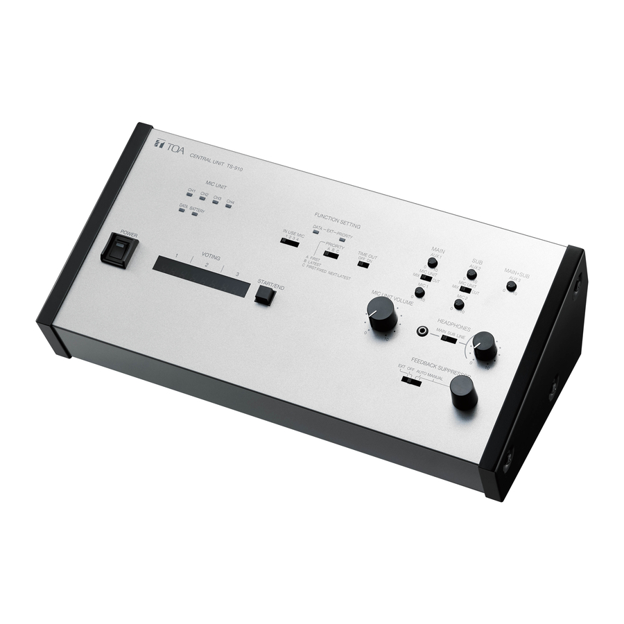
Page 8: Nomenclature And Functions
4. NOMENCLATURE AND FUNCTIONS 4.1. Central Unit TS-910 [Top] 12 13 15 16 1. Power switch 6. External control priority indicator Setting this switch to the ON position causes the Either lights or flashes when a PC or operation Power indicator to light. panel connected to the External Control terminal (30) or (32) performs priority operation. - Page 9 17. Speech priority selector switch CUT: S peech input from the Conference units is not output to the base language channel* Determines the priority mode when the Talk key The AUX 1 and MIC 1 input signals are not of the Conference unit is pressed. (Refer to the delivered to the recording and line outputs. separate Operating instructions.) A: First-in-first-out priority Note...
- Page 10 [Rear] 25 26 27 28 29 30 31 32 33 34 35 37 38 39 40 41 25. AUX 3 input terminal 32. External control terminal [USB] −20 dB*, 10 kΩ, unbalanced, phone jack. Connects to the external control terminal of a Connect a CD player, tape recorder, or other PC, operation panel or other connected external similar equipment to this terminal.
- Page 11 38. Graphic equalizer output terminal 43. Infrared transmitter/receiver and Expansion unit I/O terminals −20 dB*, 10 kΩ, unbalanced, RCA jack. Connect this terminal to the graphic equalizer’s Connect the Infrared Transmitter/Receiver unit, input terminal. Expansion unit, or Distributor to these terminals. [Infrared Transmitter/Receiver connection] 39. Priority chime volume control By using the YW-1022 (2-branch distributor) and/ Adjusts the output volume of the chime tone that or YW-1024 (4-branch distributor), the following...
-
Page 12: Infrared Chairman Units Ts-901 And Ts-801
4.2. Infrared Chairman Units TS-901 and TS-801 [TS-901 Top] [TS-801 Top] CHAIRMAN UNIT TS -9 0 1 CHAIRMAN UNIT T S - 8 0 1 POWER POWER PRIORITY TALK PRIORITY TALK Note: No microphone is supplied with the TS-901/801. 1. Monitor speaker speech). The indicator flashes when the unit is out Speech signals from other Conference units and of the communications service area. - Page 13 [Bottom] Remove the cover on the bottom side of the unit to expose its setting switches. Note The figure below shows the setting switch labels for both models. [TS-901 setting switch label] [TS-801 setting switch label] RESET RESTORE PRIORITY RESET RESTORE PRIORITY CHIME MUTE...
- Page 14 [Right side] 16. Monitor volume control Adjusts the output volume of the monitor speaker and right-side headphone output. 17. Monitor selector switch (TS-901 only) Selects either Base Language or Translation Language for the source to be output to the monitor speaker and headphones. 18. headphone jack Connect headphones to this jack (mini-jack). Connecting the headphone cuts off the output from the monitor speaker.
-
Page 15: Wired Chairman Units Ts-911 And Ts-811
4.3. Wired Chairman Units TS-911 and TS-811 [TS-911 Top] [TS-811 Top] PUSH PUSH Note No microphone is supplied with the TS-911/811. 1. Monitor speaker 7. Priority speech key Speech signals from other Conference units and Gives speaking priority to the current speaker. other audio signals from the Central unit are output When this key is used for speech, no other delegate from this speaker. - Page 16 [Bottom] Remove the cover on the bottom side of the unit to expose its setting switches. Note The figure below shows the setting switch labels for both models. [TS-911 setting switch label] [TS-811 setting switch label] RESET RESTORE PRIORITY RESET RESTORE PRIORITY CHIME MUTE...
- Page 17 [Right side] 14. Monitor volume control Adjusts the output volume of the monitor speaker and right-side headphone output. 15. headphone jack Connect headphones to this jack (mini-jack). Connecting the headphone cuts off the output from the monitor speaker. (Refer to the table below.) Model Output signal 14 15 TS-911 Base language or Translation language Note: Switchable by the Monitor selector switch (16).
-
Page 18: Infrared Delegate Units Ts-902 And Ts-802
[Rear] 18. Communication cable connection terminal Connects to the TS-919B4 or TS-919B1 Bridge unit with a CAT-5 LAN cable. 4.4. Infrared Delegate Units TS-902 and TS-802 [TS-902 Top] [TS-802 Top] DELEGATE UNIT T S-802 DELEGATE UNIT TS-90 2 POWER POWER TALK TALK Note: No microphone is supplied with the TS-902/802. - Page 19 7. Talk key signal access to this part of the unit, as this would prevent the unit from transmitting or receiving its When this key is pressed, both the Microphone In- required infrared signal. Use indicator (3) and the Speech indicator (6) light, and the microphone turns on.
- Page 20 [Right side] 11. Monitor volume control Adjusts the output volume of the monitor speaker and right-side headphone output. 12. Monitor selector switch (TS-902 only) Selects either Base Language or Translation Language for the source to be output to the monitor speaker and headphone. 13. headphone jack Connect headphones to this jack (mini-jack). Connecting the headphone cuts off the output from the monitor speaker.
-
Page 21: Wired Delegate Units Ts-912 And Ts-812
4.5. Wired Delegate Units TS-912 and TS-812 [TS-912 Top] [TS-812 Top] PUSH PUSH Note No microphone is supplied with the TS-912/812. 4. Voting keys (TS-912 only) 1. Monitor speaker Speech signals from other Conference units and Use these keys to start, end, and cast voting. The other audio signals from the Central unit are output voting status indicator is provided on each key. - Page 22 [Bottom] Remove the cover on the bottom side of the unit to expose its setting switches. Note The figure below shows the setting switch label. NOT USE UNIT ID 8. Unit address number setting switch Set the unit address number (001 – 192), taking Set a numeral for the ones place and tens place.
- Page 23 [Left side] 12. headphone volume control Adjusts the output volume of the left-side headphone output. 10 12 [Rear] 13. Communication cable connection terminal Connects to the TS-919B4 or TS-919B1 Bridge unit with a CAT-5 LAN cable.
-
Page 24: Expansion Unit Ts-918
4.6. Expansion Unit TS-918 [Front] 1. Power indicator 2. Connection status indicators Lights when connecting the supplied AC adapter to The corresponding LINE indicator lights when the the DC inlet (5). TS-919B4 or TS-919B1 Bridge unit is connected to the Bridge unit connection terminal (6) and power is supplied to it. -
Page 25: Bridge Unit (4-Conference Unit Connection Type) Ts-919B4
4.7. Bridge Unit (4-Conference unit connection type) TS-919B4 [Front] 1. Connection status indicators The corresponding LINE indicator lights when the Wired Conference unit is connected to the Conference unit connection terminal BRIDGE UNIT TS-919B4 (3) and power is supplied to it. EXPANSION BRIDGE [Bottom]... -
Page 26: System Connection Examples
5. SYSTEM CONNECTION EXAMPLES External equipment connections For base language Speaker Amplifier For translation language Recording unit Graphic equalizer For base and translation languages Central unit TS-910 Infrared unit connections Infrared transmitter/receiver AC adapter Distributor (supplied with YW-1024 the TS-910) Infrared Chairman units TS-901 and TS-801 Power cord Infrared Delegate units TS-902 and TS-802... -
Page 27: Infrared Transmitter/Receiver Installation And Connections
6. INFRARED TRANSMITTER/RECEIVER INSTALLATION AND CONNECTIONS 6.1. Notes on Installation of the Infrared Transmitter/Receiver Unit Installing the Infrared Transmitter/Receiver unit in locations exposed to sunlight or in proximity to such infrared sources as fluorescent lights could result in system failures or the introduction of noise into the system. Avoid installing the Infrared Transmitter/Receiver unit in close proximity to infrared sources, as instructed below: [Avoid direct sunlight] • Cover windows with curtains or blinds to shield... -
Page 28: Infrared Service Areas
6.2. Infrared Service Areas 6.2.1. Infrared Transmitter/Receiver [TS-905] 150° Ceiling height 2.5 – 4.5 m Radius of communication area [TS-907] 90° Ceiling height 5 – 7 m Radius of communication area Model Ceiling height Radius of communication area 2.5 m Approx. - Page 29 6.2.2. Infrared Conference Unit 120° 90° 15° 120° 15° CHAIRMAN UNIT TS- 901 POWER PRIORITY TALK...
-
Page 30: Infrared Transmitter/Receiver Arrangement Examples
6.3. Infrared Transmitter/Receiver Arrangement Examples The area range that an Infrared Transmitter/Receiver unit covers differs depending on the height from the Infrared Conference units to the ceiling. (Refer to p. 28.) Arrange the Infrared Transmitter/Receiver units so that all Infrared Conference units are included in the service area. -
Page 31: Wiring Between The Infrared Transmitter/Receiver Unit And The Central Unit
6.4. Wiring between the Infrared Transmitter/Receiver Unit and the Central Unit 6.4.1. Notes on wiring Infrared Transmitter/Receiver Distributor Central unit When two or more Infrared Transmitter/Receiver units receive infrared signals from the Infrared Conference units, the signal reception level increases if input signals to each Transmitter/Receiver unit are in phase. If not in phase, the signal reception level may decrease. - Page 32 6.4.3. Wiring examples (Example 1) Infrared transmitter/receiver All cables for "N" must be identical in length when the Infrared Transmitter/Receiver unit and the Central unit are installed in the same space. Central unit (Example 2) Infrared transmitter/receiver Distributor When installing in the same space, • All "L" cables must be identical in length • All "M" cables must be identical in length. Note To facilitate the unification of coaxial cables used in different connections into the same length, it is highly recommended that wiring from the Central unit to the distributor mounted in a ceiling be performed with...
-
Page 33: Mounting The Infrared Transmitter/Receiver Unit
6.5. Mounting the Infrared Transmitter/Receiver Unit 6.5.1. Ceiling mounting 83.5 mm ø68 5 mm Coaxial cable Mounting plate (supplied with the TS-905/907) Mounting screw Tabs (3 places) Notes The screws supplied with the TS-905 and TS907 • are used for mounting it to the microphone stand. (Refer to the next page.) Mounting screws for ceiling or wall are not supplied •... - Page 34 6.5.2. Mounting on a microphone stand Anti-drop screws M3 x 6 (supplied with the TS-905/907) Infrared transmitter/receiver TS-905/907 Stand mounting frame (supplied with the TS-905/907) Coaxial cable Tabs (3 places) Rotate to fix. Mounting plate (supplied with the TS-905/907) U 5/16 – NS 5/8 thread adapter (supplied with the TS-905*/907)
-
Page 35: Connections Between The Infrared Transmitter/Receiver Unit And The Central Unit
6.6. Connections between the Infrared Transmitter/Receiver Unit and the Central Unit 6.6.1. Connecting Use the coaxial cable with a BNC connector to connect the Infrared Transmitter/Receiver unit to the Central unit. Coaxial cable Central unit TS-910 (rear panel) Infrared transmitter/receiver TS-905/907 Live status indicator Short circuit indicator... - Page 36 6.6.2. Coaxial cable processing Coaxial cable Applicable BNC plug RG-59/U YA-641 (1 piece per package), CC-4900 (10 pieces per package), and CC-4901 (10 pieces per package) RG-6/U YA-641 (1 piece per package), CC-4900 (10 pieces per package) RG-11/U YA-642 (1 piece per package) Note: Purchase both the coaxial cable and the required BNC plugs separately.
- Page 37 Step 6. Insert the coaxial cable into the clamping fixture. Clamping fixture Conductor Step 7. Insert the clamping fixture assembly into the plug and then solder the conductor. Solder. Step 8. Insert the plug into the BNC connector. BNC connector Step 9. Clamp the connector by tightening the clamping fixture. Clamping BNC connector fixture (Finished) Attaching a YA-641 BNC Plug to the RG-6/U Cable Braided shield Step 1.
- Page 38 Step 4. Disassemble the BNC plug as shown in the figure at right. Clamping BNC connector Plug fixture Step 5. Insert the coaxial cable into the clamping fixture. Clamping fixture Conductor Step 6. Insert the clamping fixture assembly into the plug and then solder the conductor.
-
Page 39: Wired Conference Unit Connection
7. WIRED CONFERENCE UNIT CONNECTION When connecting the Wired Conference units to the Central unit, the Expansion unit and the Bridge unit must be installed between them. Central unit TS-910 Bridge unit Expansion unit TS-918 TS-919B1/919B4 BRIDGE UNIT TS-919B1 EXPANSION BRIDGE Coaxial cable Wired Conference unit... - Page 40 7.1.2. Connecting 3 or 4 Expansion units Use the YW-1024 Distributor (4-branch distribution). Connection of 3 Expansion units will leave one of the four terminals idle, however no problems will result. Expansion unit TS-918 Central unit TS-910 Expansion unit TS-918 Distributor YW-1024 Expansion unit TS-918 (4 branches)
-
Page 41: Expansion Unit, Bridge Unit, And Wired Conference Unit Connections
• A system may have Expansion units that both pass through and do not pass through the Distributor. Central unit TS-910 Expansion unit TS-918 Distributor YW-1022 Expansion unit TS-918 (2 branches) or YW-1024 (4 branches) Coaxial cable Expansion unit TS-918 7.2. Expansion unit, Bridge Unit, and Wired Conference Unit Connections Bridge unit When connecting the Expansion unit to the Expansion unit TS-918 TS-919B1/919B4 Wired Conference Unit, the Bridge unit must... - Page 42 7.2.1. Bridge unit TS-919B1 connection Bridge unit TS-919B1 From Expansion unit TS-918 or To Bridge unit BRIDGE UNIT TS-919B1 Bridge unit TS-919B1/919B4 TS-919B1/919B4 EXPANSION BRIDGE LAN cable (CAT-5) Wired Conference unit TS-911/912/811/812 7.2.2. Bridge unit TS-919B4 connection Note Bridge unit The Bridge unit may have any TS-919B4 idle terminal among the conference...
- Page 43 7.2.4. Connecting 8 Wired Conference units to one of the Expansion unit’s terminals Bridge unit TS-919B4 BRIDGE UNIT TS-919B4 BRIDGE UNIT TS-919B4 Expansion unit TS-918 EXPANSION BRIDGE EXPANSION BRIDGE Coaxial cable Conference unit TS-911/912/811/812 LAN cable (CAT-5) Only in this case, use this terminal for connection of the 8th unit.
-
Page 44: Wiring
• There is restriction on the number of the Bridge units that can be connected to one of the Expansion unit’s Bridge unit connection terminals. (Refer to p. 42.) Bridge unit Bridge unit TS-919B4 TS-919B1 BRIDGE UNIT TS-919B1 BRIDGE UNIT TS-919B4 BRIDGE UNIT TS-919B4 EXPANSION BRIDGE Expansion unit TS-918 EXPANSION BRIDGE EXPANSION BRIDGE Coaxial cable LAN cable (CAT-5) Conference unit TS-911/912/811/812 7.3. -
Page 45: Using Wired Microphones And Sound Source Equipment
[When using no Distributor (Maximum cable distance: 200 m)] Distance between the Central unit and Expansion unit: 100 m max. Distance between the Expansion unit and each Wired Conference unit: 100 m max. Distance between the Central unit and each Wired Conference unit: 200 m max. Wired Conference unit TS-911/912/811/812 Bridge unit TS-919B4 Central unit TS-910 Expansion unit TS-918 Bridge unit TS-919B1 Maximum 100 m Maximum 100 m Maximum 200 m Coaxial cable LAN cable (CAT-5) 8. -
Page 46: Sound Source Equipment Use
8.2. Sound source equipment use Connect sound source equipment to the Central unit's AUX input and adjust its volume with the corresponding AUX input volume control. AUX 1, AUX 2, or AUX 3 input volume control Sound source Central unit TS-910 equipment (Top panel) Line output AUX 1, AUX 2, or AUX 3 (Rear panel) input terminal 9. RECORDING EQUIPMENT CONNECTION Connect the recorder's recording input terminal to the Central unit's recording output terminal. -
Page 47: Conference Unit Installation And Settings
10. CONFERENCE UNIT INSTALLATION AND SETTINGS Step 1. Use a screwdriver to set the Unit (Inside of the cover) address number setting switch Conference unit located on the unit’s bottom side. NOT USE (bottom side) Hundreds digit Set a numeral for the ones place and tens place. -
Page 48: Infrared Conference Unit Power Supply
11. INFRARED CONFERENCE UNIT POWER SUPPLY Use either the optional BP-900 Lithium-Ion Battery or the AD-0910 AC Adapter for the power supply of the Infrared Conference units. 11.1. BP-900 Lithium-Ion Battery Note Before using the BP-900 battery, be sure to carefully read the instructions on its use described in the manual enclosed with the BP-900. -
Page 49: Bp-900 Lithium-Ion Battery
11.1.2. Recharging Use the BC-900 Battery Charger to recharge the BP-900 Lithium-Ion Battery. BP-900 Lithium-Ion Battery Power cord (supplied with the BC-900) Charging status indicator (Red/green) AC adapter (supplied with the BC-900) Power switch Power input terminal BC-900 Battery Charger Step 1. -
Page 50: Ad-0910 Ac Adapter
11.2. AD-0910 AC Adapter Connect the AD-0910 AC Adapter to the DC Inlet located on the left side panel of the Infrared Conference units. TS-901/902/801/802 DC inlet Power cord AC Adapter (supplied with the AD-0910) AD-0910... -
Page 51: Rack Mounting
Screws removed in Step 1 (6 screws) Fiber washer (supplied with the MB-TS900) Rack mounting screw 5 x 12 (supplied with the MB-TS900) Note Supplied 5 x 12 rack mounting screws are designed specifically for TOA's equipment rack. Do not use them for other rack mounting. -
Page 52: Mounting The Expansion Unit On A Rack
12.2. Mounting the Expansion Unit on a Rack • Use the optional MB-15B-BK hardware set when mounting a single unit. Remove 8 screws located on both sides of the unit, then attach the optional hardware as shown below. 3 x 8 tapping screw* Component parts and accessories of MB-15B-BK 3 x 14 tapping screw*... -
Page 53: Installation Status Confirmation
13. INSTALLATION STATUS CONFIRMATION Installation status for the Expansion unit, Bridge unit, Infrared Transmitter/Receiver unit, and Conference units can be checked from the Central unit. Switch on the power to the Conference units to confirm their installation status after completing installation and connection. Note None of the unit's functions can be used while in installation status confirmation mode, except Priority Speech initiated from the Chairman unit. -
Page 54: Appendix (Infrared Transmitter/Receiver Connection)
14. APPENDIX (INFRARED TRANSMITTER/RECEIVER CONNECTION) This chapter describes how to find the maximum cable length between the Central unit and the Infrared Transmitter/Receiver unit. Values calculated here are given only as guidelines, since they can vary depending on ambient building conditions and the Infrared Transmitter/Receiver unit. - Page 55 14.1.2. Computational equation • Finding the wiring loss Requirement: Total loss 20 dB Cable loss = (Length / 100) x Loss per 100 m Total loss = Cable 1 loss + Cable 2 loss + Cable 3 loss + Distributor 1 loss + Distributor 2 loss Central Unit Distributor 1 Distributor 2 Transmitter/Receiver unit Coaxial cable 1 Coaxial cable 2 Coaxial cable 3 Coaxial cable 1 loss Coaxial cable 2 loss Coaxial cable 3 loss • Finding the wiring voltage drop...
-
Page 56: Design Examples
14.2. Design Examples 14.2.1. Example : When installing 4 TS-905 Infrared Transmitter/Receiver units using 4 coaxial cables reaching from the Central unit: Infrared Transmitter/Receiver units Central unit TS-905 1) Finding the maximum cable length using maximum allowable cable losses Assuming that the type of coaxial cable used is RG-59/U, Maximum cable length L = (Coaxial cable loss / its cable loss per 100 m ) = (20 dB / 3.3 dB) x 100 m = 606 m... - Page 57 14.2.2. Example 2: When installing 4 TS-905 Infrared Transmitter/Receiver units using 1 coaxial cable reaching from the Central unit (one 4-branch distributor connected): Condition: C able length between the Distributor and the TS-905 Infrared Transmitter/Receiver unit is assumed to be 50 meters. Infrared Transmitter/Receiver units TS-905 Central unit Distributor 50 m 1) Finding the maximum cable length using maximum allowable cable losses Assuming that RG-59/U coaxial cable is used between the Distributor and the Infrared Transmitter/Receiver unit, the cable loss between the two is calculated by the following equation: Cable loss = 3.3 dB x (50 m / 100 m) = 1.65 dB...
- Page 58 2) Finding the maximum cable length using voltage drop The current flowing from the Distributor into each coaxial cable connected to the TS-905 Infrared Transmitter/ Receiver unit is 0.1 A, since the number of Infrared Transmitter/Receiver units connected to each coaxial cable is 1.
- Page 59 14.2.3. Example 3: When installing each 4 TS-905 Infrared Transmitter/Receiver units using 4 coaxial cables reaching from the Central unit (four 4-branch distributors connected): Condition: C able length between the Distributor and the TS-905 Infrared Transmitter/Receiver unit is assumed to be 50 meters. Infrared Transmitter/Receiver units TS-905 Distributor Central unit 50 m The equation and maximum cable length in this example are the same as those in Example 2 in the previous section on p.
- Page 60 14.2.4. Example 4: When installing 16 TS-905 Infrared Transmitter/Receiver units using 1 coaxial cable reaching from the Central unit (five 4-branch distributors connected): Condition: L ength between the Distributor 2 and the TS-905 Infrared Transmitter/Receiver unit is assumed to be 50 meters, and the length between Distributor 1 and Distributor 2 10 meters. Infrared Transmitter/Receiver units TS-905 Distributor 2...
- Page 61 2) Finding the maximum cable length using voltage drop The current flowing from the Distributor 2 into each coaxial cable connected to the TS-905 Infrared Transmitter/Receiver unit is 0.1 A, since the number of Infrared Transmitter/Receiver units connected to each coaxial cable is 1. Assuming that RG-59/U coaxial cable is used, the voltage drop between the Distributor 2 and the Infrared Transmitter/Receiver unit is calculated by the following equation: Voltage drop = 16.82 Ω x (50 m / 100 m) x 0.1 A...
-
Page 62: Signal Flow Diagram Inside The Central Unit
15. SIGNAL FLOW DIAGRAM INSIDE ThE CENTRAL UNIT Translation language Base language LINE REC OUT MIC 1 input AUX 1 input MIC 2 input Inter- locking AUX 2 input AUX 3 input AUX 3 output Mix/Cut switch (for base language) Audio signal from Conference units Microphone... - Page 64 Traceability Information for Europe Manufacturer: Authorized representative: TOA Corporation TOA Electronics Europe GmbH 7-2-1, Minatojima-Nakamachi, Chuo-ku, Kobe, Hyogo, Suederstrasse 282, 20537 Hamburg, Japan Germany URL: http://www.toa.jp/ 133-07-00009-04...
Need help?
Do you have a question about the TS-910 Series and is the answer not in the manual?
Questions and answers