Advertisement
Quick Links
perating Manual
Cat. 00304 8/1/09
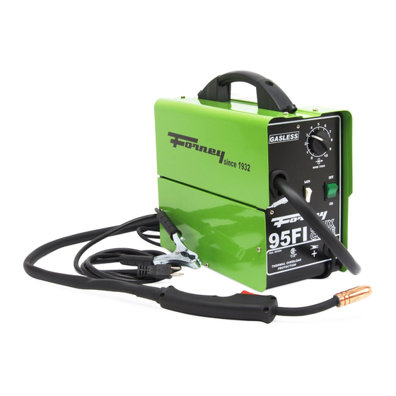
FLUX C RE
WIRE WELDER
95FI
TwecofJ
Style Torch
Infin ite W ire S p eed
Multiple Power
·
Th erm al overlo ad
W elds alltypes
•
Mild
(Carbon)
•
Stainless Steel
• Cast
Iron
Complefe & Ready
Com es
with:
Operating
Set-Up
Cf!art
Spool of Flux
Extro
Wire.
Contact Tips.
Hammer
&
Brush
W elding
Face
Shi
C ontrol
settings
P rotec iion
of:
Steel
to
W eld
Manual.
Cored
Chipping
Combo
&
e
ld
Advertisement

Related Manuals for Forney 95FI


Summary of Contents for Forney 95FI
- Page 1 Manual Cat. 00304 8/1/09 FLUX C RE WIRE WELDER 95FI TwecofJ Style Torch Infin ite W ire S p eed C ontrol settings Multiple Power · Th erm al overlo ad P rotec iion W elds alltypes • Mild...
- Page 2 Purchaser will: 1-800-521-6038 A) Contact Forney's customer service at B) Provide dated proof purchase (typically a purchase Provide the serial number. Registering your welder this process. D) Deliver...
- Page 4 indication that the step contains is an next that might procedure be injurious to a person if proper safety precautions are not heeded. procedure preceded a CAUTION is indication that the next step contains a pro that might damage the equipment cedure being used.
- Page 5 d. any metal parts on the electrode holder, or wire feed gun. Do not weld in a damp area or come in • contact with a moist or wet urface. • Do not attempt to weld if a· n y part of clothing or body is wet.
- Page 6 helmet and replace any cracked or bro wear flammable hair preparations. ken filter lenses IMMEDIATELY. Do not weld in an area until it is checked • Do not allow the uninsulated portion and cleared of combustible and/or flam of the wire feed gun to touch the ground mable materials.
- Page 7 not adequate to exchange aff fumes and gasses generated during welding process with fresh air, do not weld unless you (the welder) and all bystanders are wearing air-supplied respirators. • Do not heat metals coated with, or that contain, materials that produce toxic fumes (such as galvanized steel), unless the coating is removed.
- Page 8 OSHA office or U.S. Dept. of Labor OSHA, Office of Public Affairs, Room N3647, 200 Constitution Ave., W ashington, DC 20210 - www.osha.gov • CSA Standard W 117 .2 Code for SAFE TY IN W ELDING AND CUTTING. obtainablefromCanadianStandards Association, 178 Rexdale Blvd., Etobicoke, O ntario M 9W 1R 3 w w w .csa.ca...
- Page 9 cycle rating of a welder defines duty how long the operator can weld and how long the welder must be rested and cooled. Duty cyc\e expressed as a percentage of 10 minutes and represents the maximum welding time allowed. The balance of the 10- cycle is for cooling.
- Page 10 the speed at which the welder feeds wire to is the slowest wire feed speed, gun. 1 the highest. You will need adjust ·"tune-in" your wire speed for different welding conditions (thickness of metals, metal type, wire size, etc.). When the wire speed is prop erly "tuned-in"...
-
Page 11: Extension Cords
operated on inadequate or excessive power. EXTENSION CORDS Foroptimum welder performance, an extension cord should not be used unless absolutely nec essary. If necessary, care must be taken in selecting an extension cord appropriate for use with your specific welder. Select properly grounded extension cord that will mate directly with the ac power... - Page 12 Handle Cover Handle Extra Material Dark Glass . . . f 8 l - - - - R e ta in in g Clip Retaining Retaining Tabs Clip Figure 2. Face Shield Assembly...
- Page 13 WARNING ARC RAYS CAN INJURE EYESI To reduce the risk arc flash, make certain that the welding wire, when it finally comes out of the end of the gun, does not touch the ground clamp or any grounded piece of metal.
-
Page 14: Preparations For Welding
select minimum and aximum eat settings. Refer to the Suggested Settings Chart on p.29 of this manual for suggestions on which heat setting to use for your welding job. PREPARATIONS FOR WELDING An important factor in making a satisfactory This includes studying preparation. - Page 15 37.5" p;@1 BEVEL JOINT SINGLE BEVEL JOINT DOUBLE 31'32" TO Hs - CLOSED JOINT oo· -.-. OPEN JOINT ·}(,_ ---- • DOUBLE VEE JOINT FILLET SINGLE FILLET JOtNT SINGLE. STRAP JOINT DOUBLE STRAP JOINT Figure 7. Types...
-
Page 16: Holding The Gun
process of trial and error. The best way to teach yourself how to weld is with short peri ods of practice at regular intervals. All prac tice welds should be done on scrap metal that can be discarded. Do not attempt to make any repairs on valuable equipment until you have satisfied yourself that your practice welds are of good appearance and... -
Page 17: Electric Shock Can Kill
welding gloves, a heavy long sleeved shirt, cuffless trousers, high topped shoes and a welding helmet. WARNING To prevent ELECTRIC SHOCK CAN KILL! ELECTRIC SHOCK, do not perform any welding while standing, kneeling, or lying directly on the grQunded work. WELDING TECHNIQUES MOVING THE GUN Gun travel refers to the movement of the gun... -
Page 18: Welding Positions
Figure 12. eave Bead WELDING POSITIONS three basic welding flat, There are positions: horizontal, and vertical. (Figure 13) is the 1. The FLAT POSITION of the welding positions and is proba easiest bly the one you have been using thus far. It is best you can weld in the flat position all possible as good results are easier to... - Page 19 Figure 16. Butt Joints Fillet Weld Joints. Most fillet weld joints, on metals of moderate to heavy thickness,·will require multiple pass welds to produce a strong joint. The illustrations in Figure 17 show the sequence of laying · m ultiple pass beads into a T fillet joint and a1ap fillet joint.
-
Page 20: Spot Welding Instructions
each side of seam. joint Select the wire diameter, heat setting, and tune-in the wire speed as if you were welding the same thickness material with a continuous bead. SPOT WELDING INSTRUCTIONS 1. Select the wire diameter and · h eat setting recommended above the method spot welding you intend to use. - Page 21 nozzle results when spatter SHORTED buildup bridges the insulation in the nozzle allowing welding current to flow through it as well as the contact tip. When shorted, a noz steal wetding current from the wire will contacts the grounded work whenever piece.
- Page 22 ..,.._Plastic T r ig g e r , - - - Block Live Wire T e r m in a l - - ---..a. Switch L i n e r - - - - - - + + - Handle C a s i n g - - - - Switch Wire...
- Page 23 4. Poor ground co size Wrong 6. loose gun conn gun assembly Wire is jamming or "birdnesting" at tensio much 2. Gun liner worn the drive roller 3. Contact tip is cl aged 4.Liner stretched Wire burns back to contact tip 1.
- Page 26 FRONT,BO 05000172 85221 44120131 TRANSFO 85280 04600234 CABLE CL 85209 21905041 PLASTIC M 85243 21905007 DARK GLA 85241 21905039 HAMMER 85242...
- Page 31 - - - NCE 932...
- Page 32 Forney Industries, Inc. 1-800-521-6038 www.forneyind.com...
Need help?
Do you have a question about the 95FI and is the answer not in the manual?
Questions and answers