Table of Contents
Advertisement
Quick Links
g Ma ual
00301 10/1/09
I fi ite Power Setti gs
Thermal Overload Protectio
Welds all types of:
• Mild (Carbon) Steel
• Stainless Steel
• Cast Iron
Complete & Ready to Weld
Comes with: Operating ManuaL
Electrode Holder, Ground Clamp,
Chipping Hammer & Brush Combo,
Welding Face Shield, & Starter
Pack of Electrodes
M a ual P art N o.:
C at#
0025
Effective Date:
October
, 2009
Advertisement
Table of Contents

Summary of Contents for Forney 96FI-A
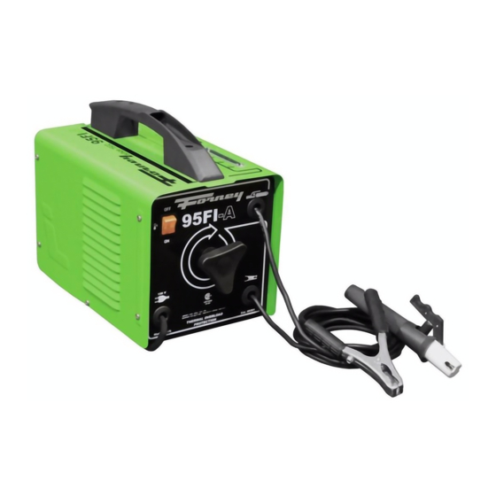
- Page 1 g Ma ual 00301 10/1/09 I fi ite Power Setti gs Thermal Overload Protectio Welds all types of: • Mild (Carbon) Steel • Stainless Steel • Cast Iron Complete & Ready to Weld Comes with: Operating ManuaL Electrode Holder, Ground Clamp, Chipping Hammer &...
- Page 2 " " '''v 'lit lr . r - . warrants to its original retail purchaser that the new Forney equipment sold after the limi t ed warranty is free of defects in material and workmanship at the time shipped by Forney.
- Page 4 A procedure step preceded by a WARNING is an indication that the next step contains a procedure that might be injurious to a person if proper safety precautions are not heeded. A procedure preceded by a CAUTION is an indication that the next step contains a pro cedure that might damage the equipment being used.
- Page 5 b. the ground clamp, c. the electrode or welding wire, d. any metal parts on the electrode holder, or wire feed gun. Do not weld in a damp area or come in • contact with a moist or wet surface. Do not attempt to weld if any part of •...
- Page 6 either remove or cover with something non-flammable and non-reflective. Reflective arc rays can also cause skin burn in addition to eye injury. • IRE HAZARDS • WARNING • IRE OR EXPLOSION CAN CAUSE DEATH, INJURY, AND PROPERTY DAM· To reduce the risk of death, injury, or property damage from fire or explosion, read, understand, and follow the following safety instructions.
-
Page 7: Fume Hazards
arc or its ultraviolet radiation. These solid, safe floor, preferably concrete or masonry, not tiled, carpeted, or made of actions can cause PHOSGENE, a HIGH any other flammable material. LY TOXIC gas to form, along with other • Protect flammable walls, ceilings, and lung and eye-irritating gasses. - Page 8 ADDITIONAL SA ETY IN ORMATION WELDER SPECI ICATIONS For additional information concerning weld ing safety, refer to the following standards and comply with them as applicable. Your new stick (SMAW) welder is designed for maintenance and sheet metal fabrication. • ANSI Standard 249.1 - SAFETY IN WELDING AND CUTTING -obtainable Table 1.
-
Page 9: Welder Installation
Select a properly grounded extension cord that WELDER INSTALLATION will mate directly with the power source recepta cle and the welder power cord without the use POWER SOURCE CONNECTION of adapters. Make certain that the extension is properly wired and in good electrical condition. POWER REQUIREMENTS Extension cords must be a #12 gauge cord at This welder is designed to operate on a proper... -
Page 10: Preparation For Welding
electrode holder ( item Once protective dark glass has been Note: All connections should be a good metal installed into face shield, secure it in place contact. Clean with a wire brush where nec with the retaining clips. Align the holes on each of the retaining clips with the pins on essary. -
Page 11: Welding Technique
WELDING TECHNIQUE nation, you have almost certainly failed to achieve the correct combination Do not 1. Plug your welder into the correct socket worry as practice will soon cure this. The and switch on using the ON/OFF switch following tips on welding pitfalls should (Item B). -
Page 12: Maintenance And Servicing
Electrode moved over workpiece too The perfect weld -with the correct combi slowly -this causes a very wide and nation of arc length, amperage regulation heavy deposit which overlaps at the and inclination of the electrode you will, sides. It is wasteful in terms of both time with practice, produce the perfect weld. -
Page 13: Troubleshooting
TROUBLESHOOTING PROBLEM PROBABLE CAUSE POSSIBLE SOLUTION The Thermal Overload Power source stops. Thermal Overload Protection Protection automatically resets activated due to overload. when the transformer has cooled (approx. 15 minutes) Power switch on Bad connection between ground Clean or wire brush the clamp and workpiece. -
Page 14: Types Of Joints
TYPES OF JOINTS OPEN SQUARE BUTT JOINT ...---.----11 - 1 CORNER JOINT - + l r - Gapvarlesfrom mmlo4. mm depending onplat£!tllid;ness. SINGLE VEE BUTT JOINT SINGLE FILLET LAP JOINT N O T L E S S TH A N 7 0 L...---..-1 4 r - 1.6mm... -
Page 15: Wiring Diagram
WIRING DIAGRAM · · · - · - ·- , < 120V 60Hz... - Page 16 21905039 85242 HAMMER-BRUS...
-
Page 17: Parts Diagram
PARTS DIAGRAM D O D ·... - Page 18 IN C E1932...
- Page 19 or ey I dustries, I c. 1- 00-521- 03 www.forneyind.com...


Need help?
Do you have a question about the 96FI-A and is the answer not in the manual?
Questions and answers