Advertisement
Quick Links
ASSEMBLY INSTRUCTIONS
ASSEMBLY RATING
The Assembly Rating is a 5-point system that
show the degree of effort needed in assem-
bling a specific product (with 1 being easy and
5 being difficult). For most products, two per-
sons are recommended.
EASY
YNJ-317-4
TOOLS REQUIRED FOR ASSEMBLY
Allen Wrench
Phillips Screwdriver
Hammer
DIFFICULT
Page 1 of 16
(Included)
(Not Included)
(Not Included)
2 PERSONS RECOMMENDED
Advertisement

Related Manuals for Furniture of America YNJ-317-4


Summary of Contents for Furniture of America YNJ-317-4
- Page 1 ASSEMBLY INSTRUCTIONS YNJ-317-4 TOOLS REQUIRED FOR ASSEMBLY ASSEMBLY RATING Allen Wrench The Assembly Rating is a 5-point system that (Included) Phillips Screwdriver show the degree of effort needed in assem- bling a specific product (with 1 being easy and Hammer (Not Included) 5 being difficult).
- Page 2 Thank you for your purchase! We hope you will enjoy your new product for many years to come. Our commitment to providing quality products does not simply end when a purchase is made. We stand behind our products and will provide any support needed in order for you to fully enjoy your purchase.
- Page 3 Page 3 of 16...
- Page 4 PRE-ASSEMBLY INTRODUCTION Unless you are particularly adept at assembling flat-pack/knock-down furniture, we understand building ready-to-assemble furniture can be a frustrating experience for some. To help avoid confusion and to make the assembly process quicker and smoother, we have provided some helpful tips.
- Page 5 CAM LOCK FASTENER ASSEMBLY INSTRUCTIONS Page 5 of 16...
-
Page 6: Parts List
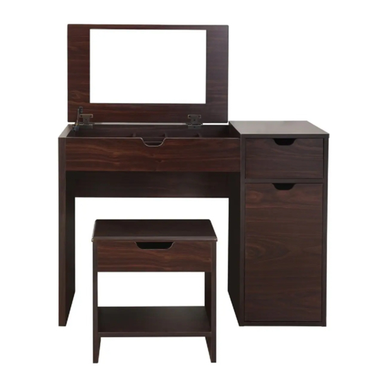
VANITY TABLE AND STOOL SET ASSEMBLY INSTRUCTIONS MODEL # YNJ-317-4 Please keep for future reference PARTS LIST DIMENSIONS 36.7”(W) X 15.7”(D) X 27.9”(H) 2PCS 2PCS DIMENSIONS 15.4”(W) X 9.8”(D) X 16.4”(H) Before you begin, please read “Assembly and Care Advice”, “Pre- Assembly Introduction”... - Page 7 VANITY TABLE ASSEMBLY STEP1 Hardware #1 = 10pcs Insert the cam bolts (1) into the holes and secure using a Phillips screwdriver. STEP2 Hardware #1 = 10pcs Page 7 of...
- Page 8 VANITY TABLE ASSEMBLY STEP3 Hardware #3 = 2pcs outer Hardware #5 = 2 sets + 4 screws Hardware #9 = 2 outer + 4 screws inner 1. Remove the inner part 9 of the rails by First remove the inner slide from the outer slide of the runner by pushing down on the tab to sliding out of the outer part 9 .
- Page 9 VANITY TABLE ASSEMBLY STEP5 Hardware #2 = 5pcs Hardware #3 = 4pcs Hardware #9 = 2 inner + 4 screws 2. Align the INNER part of 9 to the holes along the side of D , then insert the screws and secure. No t e: A s s em b l e Par t F c o m p l et el y f i r s t b ef o r e as s em b l i n g t w o i n n er s l i d es...
- Page 10 VANITY TABLE ASSEMBLY STEP7 Hardware #1 = 4pcs Hardware #11 = 2 hinges + 6 screws STEP8 Refer to page #5 for cam lock assembly. Hardware #2 = 4pcs Page 10 of...
- Page 11 VANITY TABLE ASSEMBLY STEP9 Hardware #1 = 3pcs Hardware #2 = 6pcs Hardware #3 = 10pcs Refer to page #5 for cam lock assembly. STEP10 Hardware #2 = 6pcs Hardware #3 = 2pcs Refer to page #5 for cam lock assembly. Page 11 of 16...
- Page 12 VANITY TABLE ASSEMBLY STEP11 Hardware #2 = 4pcs Hardware #7 = 6pcs Note: Insert Part U first before assembling Part S. Refer to page #5 for cam lock assembly. STEP12 Hardware #10 = 1 arm hinge + 2 screws Page 12 of 16...
- Page 13 VANITY TABLE ASSEMBLY STEP13 Hardware #10 = 2 screws Hardware #11 = 6 screws No t e: S ec u r e 6 s c r ew s i n t o t h e h i n g es 11 f i r s t t h en s ec u r e 2 s c r ew s i n t o t h e ar m h i n g e 10.
- Page 14 VANITY TABLE ASSEMBLY STEP15 STEP16 Hardware #6 = 2pcs Extend the two outer slides ⑤ so that they are align with the sides of the drawer. Make sure the pre-drilled holes from the drawer align with the screw holes of the slides. Secure the two screws ⑥...
- Page 15 STOOL ASSEMBLY STEP1 Hardware #11 = 2 hinges + 6 screws STEP2 Hardware #12 = 6pcs Page 15 of 16...
- Page 16 STOOL ASSEMBLY STEP3 STEP4 Hardware #7 = 4pcs Hardware #12 = 6pcs STEP5 Hardware #11 = 6 screws STOOL ASSEMBLY IS COMPLETED Make sure the table is rested on a flat surface and does not feel loose or wobbly. If it does, double check that the bolts/screws are secured and properly tightened.
Need help?
Do you have a question about the YNJ-317-4 and is the answer not in the manual?
Questions and answers