Table of Contents
Advertisement
Quick Links
Advertisement
Table of Contents

Subscribe to Our Youtube Channel
Related Manuals for CNC PYTHON XPR


Summary of Contents for CNC PYTHON XPR
- Page 1 U S E R G U I D E...
- Page 2 Without limiting the generality of the foregoing, by using or attempting to use this manual, the user expressly acknowledges that there are no warranties or representations made by CNC Factory regarding the content of this manual in terms of its accuracy or its completeness. In no event shall CNC Factory be liable for any damages whatsoever resulting from, arising out of or in connection with the use of any information provided on this manual.
-
Page 3: Table Of Contents
BASIC OPERATIONS Turning On the Router Turning Off the Router Getting Started with your Shortcuts Main Screen Operation Page CNC Operation Controls Auto Vs. Simulation Vs. Jog Mode Utilities Page CNC Utilities Controls Advanced Page Main Navigation Belt Tool Measure Screen... - Page 4 Contents STEP-BY-STEP GUIDES Checking your Alarm History Backing up your Files Activating Function Keys Executing your first (single) file Using Working List/File File Panel Label Panel Working List Step-by-Step Changing your File Extension Measuring Larger Tools Adjusting Drill Block Offsets CHECKLIST...
-
Page 5: General Information
Limited Warranty CNC Factory provides lifetime router support and warrants that it will be free of defects in workmanship and materials for a period of 18 months beginning on the date of delivery. This warranty does not include (wearable) parts consumed during normal operation or maintenance required in the ordinary course of operation. -
Page 6: General Warnings
If you do not remember the original values or are in doubt, please contact your CNC Factory technician for help reverting to the original settings. Using incorrect values may cause damage to your router or make it fail. -
Page 7: The Emergency Stop Or E-Stop
The Emergency Stop or E-stop The E-stop is a safety feature that stops all operations of the router. You have three (3) emergency stop buttons that are easily accessible while the router is operating: On the controller On both sides of the gantry To initiate an emergency stop, press the red button. -
Page 8: Maintenance
Maintenance Lubrication Our routers come with a fully automated, pressurized lubrication system for all the liner guides and ball screws. For best results, use 000 Semi-Fluid Lithium Grease. All helical racks & drill blocks require manual lubrication with Klüber Isoflex Topas L32N Special low-temperature grease. As a rule of thumb, apply 5cc of lubrication after every 40 hours of operation. -
Page 9: Connectivity
Quarterly Checks Conduct a drill block grease check. Annual Checks Schedule an on-site service with a CNC Factory technician. Connectivity The Python has USB, WiFi and ethernet connections. It only requires the internet for virtual/remote access. Configurations for your router’s connectivity will already be set-up by your technician during installation. -
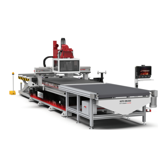
Page 10: Parts Of Your Router
P A R T S O F Y O U R R O U T E R External Parts Dust Extraction Outlet Gantry Mobile Control Cart Loading Wheels Robotic Loading Machine Safety Glass Rear Pusher Tool Carousel Suction Safety Light Encased wiring Metal foot plates... - Page 11 Drill block slot Robotic Dust Hood Auto Tool Measuring Rear pusher Device Safety Light Helical Rack & Pinion Rail System Air Pressure Monitor 2nd vacuum pump switch Vacuum Ports Control Cabinet Main Contact Digital vacuum Switch gauge Dust Extraction Outlet Mobile Control Rear pusher Cart...
-
Page 12: Notable Terminology
Ports Notable Terminology Router Refers to the entire Python XPR, including its controller/control cart. Machine Refers to the block of components responsible for cutting that is anchored to the gantry (includes the spindle, drill block, and dust hood). Whenever there is a mention of machine movement, it refers to this block... -
Page 13: Understanding Your Controller
U N D E R S T A N D I N G Y O U R C O N T R O L L E R Main Controller vs. Control Cart (ABOVE) Your actual, main controller is located inside your router cabinet. -
Page 14: Parts Of Your Control Cart
Parts of your Control Cart Camera Camera Safety Light 21” Touchscreen Cooling Fans USB Ports Desk MPG Remote Power & Signal Cord Base with lockable wheels Signal Cord Sends a network signal to the main controller. 1: Loading table power 3: Unloading table data 2: Unloading table power 4: Light curtain... - Page 15 Camera Safety Light Start Button Pause Button USB Ports E-Stop Power Vacuum Buttons Button Button Safety Light Tells the router’s current operating status. For the XPR series, the rear side of the routers have similar safety lights. • White Light- Static mode: no operation is in progress and the router is ready for a command. In this mode, the bottom right of the screen will display “Ready”...
- Page 16 USB Ports Dual ports for importing files or connecting wireless devices (keyboard, mouse). E-Stop Button Instantly shuts everything down including power to the loading and unloading tables (if available). You will need to restart all files interrupted by this shutdown. Power Button Turns the controller and the router on/off.
-
Page 17: Basic Operations
B A S I C O P E R A T I O N S Turning On the Router 1. Make sure there is no object or person around the router’s motion area to prevent collision. 2. Make sure power and air are connected to the router. 3. -
Page 18: Turning Off The Router
Turning Off the Router 1. On the Utilities screen, switch to Jog Mode by clicking on the [Jog] button. 2. Jog the machine to the tool changer side, press and hold the button on the spindle to release tool and put that tool in the tool changing station. -
Page 19: Getting Started With Your Shortcuts
Please contact support@cncfactory.com if you wish to upgrade your router. • CNC File folder [This PC > Local Disk (C:) > Network > CNC > NcFiles] This is where you upload all your files from your CAD/CAM software. When saving files here, we recommend saving all files of a single job in 1 folder. -
Page 20: Main Screen
These will make better sense once you have gone through the rest of the operations in this manual. There is no action needed on your part for this screen. This standard CNC display shows the following information: Current File... -
Page 21: Operation Page
Current tool When switching tools, make sure this is updated. The machine may crash if the numbers are Name of current file Main Tabs incorrectly assigned. Standard Controls These appear in both Utilities & Operation CNC Operation Controls tabs... -
Page 22: Cnc Operation Controls
CNC Operation Controls AUTO Tells the router to automatically perform its functions. Automatic operations will not activate unless the router is on Auto Mode. Material Selection Lets you select different material sizes. By default, it starts with the 4’x8’ size. When you switch between sizes, the router’s vacuum hold down locations will adjust to... - Page 23 Working File Selects a group of files you want to use. Pressing this button takes you to the Workinglist System Page which lets you control the execution of multiple files, including label printing. Load Loads the raw material from the hydraulic loading table and aligns it with the spoilboard.
- Page 24 Click to activate Jog Mode. Here, you can manually control the movement of the machine according to each axis. Axis buttons (for X, Y & Z) Each axis has a button for positive and negative directions. The machine moves at a maximum speed of 15,000mm/min to the corresponding direction each time an axis button is pressed.
- Page 25 Feed Rate Indicates the exact, real-time cutting speed of the machine in millimeters per minute (mm/min). In G-code programming, the feed rate value is found in the G01 (or G1) line. Spindle Rate Indicates the exact, real-time rotational speed of the spindle in revolutions per minute (RPM).
-
Page 26: Auto Vs. Simulation Vs. Jog Mode
AUTO vs SIMULATION Mode Auto Mode Each operation in Auto Mode contains a sequence of instructions for different parts. Example: [Auto] Unloading instructs the router to: • Turn off the vacuum flow • Travel to the end of the material •... -
Page 27: Utilities Page
[MAIN S C REEN > UT IL IT I ES TA B ] Name of current file Main Tabs Standard Controls These appear in both Utilities & Operation CNC Utilities Controls tabs CNC Utilities Controls Spindle Warm Up Warms up the spindle by running it and increasing its speed gradually. This process takes about 1-2 hours. - Page 28 Your fly cutter is typically set in tool holder #8. Your machine may fail if you move the fly cutter to a different tool holder without adjusting the settings on this screen. If you are switching to a different fly cutter, contact your CNC Factory technician to set up this page for you.
- Page 29 Drill Cylinder [requires upgrade] Moves the drill block up or down. Drill On [requires upgrade] Turns the drill block on/off. Spindle Forward Runs the spindle. Table Clean Cleans the table with the central dust extraction and the side air nozzles. The side nozzles require air pressure of at least 0.8 mPa in the main air system.
- Page 30 Material Thickness Click to specify the thickness of your material. The dust hood will hover just above the thickness that you specify. • If the value indicated is below the actual material thickness, there will be a gap between the dust hood and the material where dust and debris may escape.
- Page 31 Home Since your router does not require homing, this feature is only for technicians when they perform absolute encoding during installation. MDI (or Manual Data Input) Allows advanced operators to manually input their own G-code data. 1. After entering the G-code, press [F1 Ok]. The code will then appear in the filename portion of the screen.
-
Page 32: Advanced Page
Advanced Page [MAIN S C REEN > A DVA N C ED TA B ] Shows controls for individual parts and is activated when in Jog Mode. Buttons are just toggle switches to activate/deactivate individual parts. This is an advanced area used by technicians for troubleshooting. Parts not included in your router model are deactivated by default. -
Page 33: Main Navigation Belt
Main Navigation Belt [APP EAR S O N AL L TA B S ] Input preview (blue) field Machine status Whenever you input values in an • If on Auto or Jog Mode editable field, those values are • If Ready or Busy previewed here. -
Page 34: Tool Measure Screen
Tool Measure Screen The Tool Measure Screen lets you measure tools automatically. You need to measure tools only when you (a) change/adjust a bit, or (b) rearrange the position of your tools. For simplicity of use, only configure the Workpiece No. P field. The rest of the controls are for advanced use of technicians. Only change the Workpiece No. - Page 35 Entering the wrong tool number (or even entering a non-existent or empty tool holder number) may damage your machine and/or cause it to fail. When you command the machine to measure a tool, it will return whatever tool is currently on the spindle to its original place first, then proceed to measuring.
-
Page 36: Workpiece Coordinates Screen
Workpiece Coordinates Screen The Workpiece Coordinates Screen lets you use alternate workpiece starting points, instead of your default G54 coordinates. You can create and save up to 100 workpiece coordinates here. External Shift G54 Slot Any value placed here will Default Points be added or subtracted to the value of the G54 . - Page 37 Machine Absolute Zero Vs. Workpiece Zero The machine’s absolute zero is the lowest value the machine can go in the X & Y axis. It’s usually at the lower leftmost point of your router. The workpiece zero (or G54) is an offset to the workpiece home position.
-
Page 38: Vacuum Zone Setup Screen
Vacuum Zone Setup Screen Appears as a pop-up screen once clicked. This screen allows you to select which vacuum zones to activate. Depending on your router model, you may activate between 4-6 zones. By default, all zones are activated. And should you have 2 vacuum pumps, both will provide equal suction on activated zones. -
Page 39: Run Screen
Run Screen Shows the G-code of your current file as well as repeats information from the Main Screen. Run Time: Running time of the current file Accu. Time: Accumulated or total running time of the router. It goes back to zero whenever the router is reset or by pressing [F8 Clear Accum. - Page 40 F5 Tool Wear Set To modify the new diameter and height of tools when they wear down. This is an advanced machining technique. Deluche by CNC Factory, which provide you brand new bits for the We recommend using tool providers such as same price as resharpening.
-
Page 41: Function Keys Menu
Function Keys Menu [APP EAR S O N AL L TA B S ] Below are the main Function Keys on your Main Screen & Tab Pages. Function Key options usually vary according to the active operation/screen. Most function keys are for advanced use by technicians. F1 Coord Back Button For resetting and switching coordinates. - Page 42 F7: Fast Diag Displays system data. F8 About Displays general system information. more options [>>] F1 PLC Status Displays info on programmable logic controllers. Each data point corresponds to the PLC in your router. F2 Diag. Displays system data, global data, coordinates & operation log. F3 Param For editing all user parameters.
-
Page 43: Step-By-Step Guides
Checking your Alarm History If you encounter an alarm (or multiple alarms) and need the assistance of a CNC Factory technician, this page will help provide information to your technician to properly diagnose your issue. We recommend you save/take a screenshot of your most recent alarms and send it as an attachment when requesting for a service ticket. -
Page 44: Activating Function Keys
Activating Function Keys If your program does not show Function Key Shortcuts (F1, F2, etc). What your screen looks like without Function Keys 1. From the Main Screen, go to the gray menu buttons at the bottom and press [Maintain] 2. -
Page 45: Executing Your First (Single) File
4. From the Main Screen, click on the [Operation] tab. 5. Click [Select File]. 6. Select the file from the CNC file folder. 7. After you select the file, the top part of the screen should show the filename you selected 8. -
Page 46: Using Working List/File
Using Working List/File A driverless CNC feature that allows queueing of up to 999 files. (*only available in the XPR series and ideally used with the loading/unloading tables). Jobs under the working list are executed one after the other. It also shows the real-time status of each file for easy monitoring. -
Page 47: Label Panel
Label Panel The label panel info shown corresponds to the selected file from the file panel. Each file can have multiple labels. The label info will automatically change as you go down your file list. To switch between pages Shows current page (top) and total number of pages (bottom) Order... -
Page 48: Working List Step-By-Step
6. Press [F4 Clear List] and click [Ok] to delete your previous working list. When you clear your list, you are only removing them from the Working List screen and not from your CNC File Folder. 7. Press [F3 Arrange Working List]. -
Page 49: Changing Your File Extension
Changing your File Extension By default, the program runs “.nc” files. If your G-code file has a different extension (e.g. “.cnc”), you can change them by: 1. You must be on the Working List Page First. Click [Operation] tab, then [Working File]. -
Page 50: Measuring Larger Tools
Measuring Larger Tools Follow these steps to measure tools that will not fit your tool holder: 1. On the [Tool Measure] screen, press [F1 Start]. The machine will do a tool change if necessary then move to the tool measuring device. 2. -
Page 51: Adjusting Drill Block Offsets
For advanced users: Adjusting Drill Block Offsets [requires upgrade] You can adjust the drill block offset to indicate the direction (and by how much) the machine needs to travel in order for the drill block to bore at the same location where the spindle did previously. 1. -
Page 52: Checklist
C H E C K L I S T I know how to: Keep a safe working environment Contact customer support Use the emergency stop Perform router maintenance Use the controller Use the MPG remote Turn on the router Turn off the router Import files to my controller desktop Access the Python program Access the Operation and Utilities pages... - Page 53 Python XPR User Manual © 2021 CNC Factory...
Need help?
Do you have a question about the PYTHON XPR and is the answer not in the manual?
Questions and answers