Table of Contents
Advertisement
Quick Links
Advertisement
Table of Contents

Related Manuals for AC Infinity CLOUDLINE A


Summary of Contents for AC Infinity CLOUDLINE A
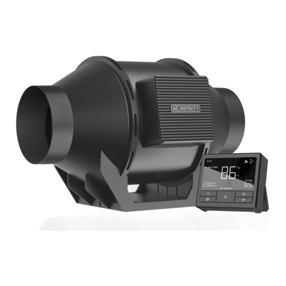
- Page 1 CLOUDLINE A/B MIXED FLOW INLINE FAN SYSTEMS USER MANUAL USER MANUAL...
- Page 3 WELCOME Thank you for choosing AC Infinity. We are committed to product quality and friendly customer service. If you have any questions or suggestions, please don’t hesitate to contact us. Visit www.acinfinity.com and click contact for our contact information. EMAIL LOCATION support@acinfinity.com...
- Page 4 MANUAL CODE CLAB2109X1 PRODUCT MODEL UPC-A CLOUDLINE A4 AI-CLA4 819137021747 CLOUDLINE A6 AI-CLA6 819137021754 CLOUDLINE A8 AI-CLA8 819137021761 CLOUDLINE B4 AI-CLB4 819137021778 CLOUDLINE B6 AI-CLB6 819137021785 CLOUDLINE B8 AI-CLB8 819137021792...
-
Page 5: Manual Index
Page 23 Adding More Fans ................. Page 27 Universal Infinity System ............... Page 28 Cleaning ..................Page 29 Programming ................. Page 31 Other Settings ................Page 42 ....................Page 43 Other AC Infinity Products ............. Page 45 Warranty ..................Page 46... -
Page 6: Key Features
KEY FEATURES QUIET PWM MOTOR STATOR BLADE FANS SMART CONTROLLER PWM-controlled motor features Hydro-mechanical stator Monitors temperature using precise speed control, reduced blades enable efficient airflow included 6” probe. Features rotor noise, and energy-efficient delivery in high static pressure two UIS ports with climate EC voltage. -
Page 7: Product Contents
PRODUCT CONTENTS CLOUDLINE A-Series SPEED UIS F - 4PIN M WOOD SCREWS ADAPTER (WALL MOUNT) CONTROLLER (x1) (x1) (x1) CLOUDLINE B-Series SMART TEMP. PROBE WOOD SCREWS CONTROLLER PROBE MOUNT (WALL HANG) (x1) (x1) (x1) (x2) FAN UNIT (Included in both A-Series and B-Series) - Page 8 PRODUCT CONTENTS...
-
Page 9: Installation
INSTALLATION MOUNTING STEP 1 Unscrew the bolts on both sides from the plastic rings using a Philips screwdriver. STEP 2 Remove the motor box from the flange bracket. Remove the wind circle between the motor box and the intake flange. - Page 10 INSTALLATION MOUNTING STEP 3 Use the flange bracket to set your desired fan position. Mark the four mounting holes. STEP 4 Drill four holes into the marked locations. Make sure your mounting area is structurally sound and free from obstruction.
- Page 11 INSTALLATION MOUNTING STEP 5 If you are mounting onto anything other than a wood support or stud, insert the included four wall anchors into the drilled mounting holes. You may need to use a hammer to secure them through the holes. STEP 6 Align the flange bracket’s holes with the wall anchors.
- Page 12 INSTALLATION MOUNTING STEP 7 Place the wind circle back into the intake flange. STEP 8 Slide the motor box back into the flange bracket, making sure its airflow arrow is pointing in the same direction as the flange bracket’s arrow. Screw the bolts back into the plastic rings to secure the motor box to the flange bracket.
- Page 13 INSTALLATION MOUNTING STEP 9 If installing ducting, use the included duct clamps to secure it to either end of the duct fan, making sure there is a tight seal. Tighten the duct clamps using a flathead screwdriver.
- Page 14 INSTALLATION HANGING - ROPE CLIPS STEP 10(a) - Hanging Upward If installing with rope hangers (sold separately), loop the ropes around the flanges and tighten the rope to secure the fan. STEP 10(b) - Hanging Downward Loop the two rope hangers around a pole and the fan's bracket.
- Page 15 INSTALLATION HANGING - STRAPS STEP 1 Loop the strap around the bracket and a pole. STEP 2 Slip the strap through the inner ladder lock slot from the bottom.
- Page 16 INSTALLATION HANGING - STRAPS STEP 3 Route the strap into the outer ladder lock slot from the top. Adjust the length of the completed loop as needed. STEP 4 Tuck the loose end through the center gap of the ladder lock to secure the loop.
- Page 17 INSTALLATION HANGING - STRAPS STEP 5(a) - Hanging Downward Let the fan hang by the pole once the straps are secure. Make sure the fan's airflow arrow is pointing towards your desired direction. STEP 5(b) - Hanging Upward To hang the fan right-side up, loop and tighten the straps, as shown in steps 1-4, around the pole.
- Page 18 INSTALLATION MOTOR CAP STEP 1 Unscrew the motor cap using a screwdriver. STEP 2 Rotate the motor cap to your desired orientation. Reapply the screws. Rotating the motor cap will not void your warranty.
- Page 19 INSTALLATION CONFIGURATION SET-UP INTAKE AND EXHAUST This fan can be used as either an intake fan or an exhaust fan in grow rooms and larger grow tents. To achieve optimal whole space ventilation, the intake fan or opening - if not using a fan - must be situated at a bottom corner of your grow space.
- Page 20 POWERING AND SETUP A-SERIES STEP 1 Plug the duct fan’s UIS connector into the speed controller. STEP 2 Plug the fan’s power cord into an AC power outlet to power the fan and controller.
- Page 21 POWERING AND SETUP B-SERIES STEP 1 You may use the included tie mounts, wood screws, and zip ties to cable manage the cords. Secure the tie mounts onto a surface using the wood screws. Loop the zip ties around the cords into the tie mounts.
- Page 22 POWERING AND SETUP B-SERIES STEP 3 Plug the temperature probe into the controller’s 3.5mm jack. Set the probe near your plants in your grow tent for the most accurate reading. Keep the probe cord away from your HID* grow light ballast's power cord to ensure the controller properly detects climate conditions.
-
Page 23: Controller Mounting
CONTROLLER MOUNTING A-SERIES MAGNET MOUNTING Mount the controller using the magnet located on its backside. - Page 24 CONTROLLER MOUNTING B-SERIES STEP 1 Locate a spot free of obstruction and secure the anchors into your wall. Twist the wood screws into the anchors. STEP 2(a) Plug in your fan's UIS plug and sensor probe. Route the cords down through the kickstand's grooves.
- Page 25 CONTROLLER MOUNTING STEP 2(b) Cords may be routed into or outside of the kickstand grooves, through a cut hole behind the controller. MAGNET MOUNTING You may also mount the controller using the magnet located behind the label.
- Page 26 CONTROLLER MOUNTING KICKSTANDING Open the stand behind the controller to set it tilted on your desktop.
- Page 27 ADDING MORE FANS The smart controller for the CLOUDLINE B-Series has an additional port so that you can add an A-Series fan to power and control two fans together. Please see below for limitations. B-SERIES CONTROLLER Smart controllers for B-Series models with EC motors can support two fans of any size. The two EC-motor fans must be plugged in to an outlet to power the fans and controller.
- Page 28 Create independent timers and schedules for customized activation in your desired timeframe. Your grow system can be regulated using your controller hub or remotely on the AC Infinity app (paired with compatible controllers), where you will have access to automation programming and climate data.
- Page 29 CLEANING STEP 1 Remove the motor box from the mounting flange. Refer to steps 1-2 on page 9 to learn how to remove the motor box. STEP 2 Use a damp cloth to clear the impeller and fan blades of any dust and debris. Remove the wind circle in between the motor box and input flange.
- Page 30 CLEANING STEP 3 Clear the stator blades of any dust and debris on the opposite end. Clean the area inside the output and exhaust flanges. STEP 4 Secure the motor box onto the mounting flanges. Refer to steps 7-9 on page 12-13 to learn how to secure the motor box.
-
Page 31: Powering On/Off
PROGRAMMING A-SERIES FAN SPEED ADJUSTING The controller features a single button that controls the fan speed from 0-10. Pressing the speed button increases the fan speed in one unit increments. Pressing the button at the 10 setting will set the fan speed back to 0. Fan Speed Indicator POWERING ON/OFF... - Page 32 PROGRAMMING B-SERIES 1. POWER BUTTON 2. MODE BUTTON 3. SETTING BUTTON Switches between the OFF and Cycles through the controller’s modes: Cycles through the controller’s ON modes. Pressing this button OFF, ON, AUTO TEMPERATURE (2 settings: DISPLAY, F/C, will bring the controller to OFF Triggers), TIMER to ON, TIMER to CALIBRATION, and mode.
-
Page 33: Power Mode Setting
PROGRAMMING POWER MODE SETTING Pressing the power button will cycle between the controller’s OFF Mode and ON Mode. OFF MODE Your fan will not run while in this mode. The fan speed set here establishes the minimum speed in the other modes. When the fan is triggered to turn OFF in all other modes, it will instead run at the speed set here. -
Page 34: Controller Modes
PROGRAMMING CONTROLLER MODES Pressing the mode button will cycle through the controller’s available programming modes: OFF, ON, AUTO TEMPERATURE (2 Triggers), TIMER to ON, TIMER to OFF, and CYCLE (ON and OFF). OFF MODE Your fan will not run while in this mode. The fan speed set here establishes the minimum speed in the other modes. - Page 35 PROGRAMMING AUTO MODE: HIGH TEMPERATURE TRIGGER Pressing the up or down button sets the high temperature trigger. The fan will activate if the probe’s reading meets or exceeds this threshold. Once triggered, the fan will gradually ramp up to the speed set in ON mode.
- Page 36 PROGRAMMING TIMER TO ON MODE Pressing the up or down button sets a countdown time. Once the timer ends, the fan will trigger to run at the speed set in ON mode. If there is a speed set in OFF mode greater than 0, the fan will run at that speed during the countdown.
- Page 37 PROGRAMMING CYCLE MODE (ON & OFF) Set an on duration and an off duration for the fan to cycle through continuously. Press the up or down button to first set a duration for the fan to activate. Then press the mode button again and set a dura- tion for the fan to deactivate.
-
Page 38: Controller Settings
PROGRAMMING CONTROLLER SETTINGS Press the setting button will cycle through the controller’s available settings: DISPLAY, F/C, CALIB. T°, and TRANS. T°. DISPLAY SETTING Adjusts the display brightness and auto-dimming. Press the up or down button to cycle through levels 1, 2, 3, A2 and A3;... - Page 39 PROGRAMMING °F/°C SETTING Changes the displayed units to Fahrenheit or Celsius. Press the up or down button to cycle through F and C. All displayed units will automatically convert when adjusting this setting. CALIBRATION TEMPERATURE SETTING Adjusts the temperature reading the sensor probe is measuring.
- Page 40 PROGRAMMING TRANSITION TEMPERATURE SETTING Adjusts the transition threshold between the fan speeds in the AUTO Mode temperature triggers. Press the up or down button to cycle through 0°F to 8°F (0°C to 4°C) and set a transition threshold. The fan speed will be set one level above the OFF Mode speed when the sensor temperature first meets or exceeds the high temperature trigger.
- Page 41 PROGRAMMING ALERT ICONS The alert icons are displayed at the top of the screen. Icons may flash when the controller signals an alert to tell you a particular function or alarm is being triggered. CONTROLLER LOCK ALERT This icon is visible when the controller has been locked. The icon will flash to alert you that the controller is locked if you try to change the mode or settings.
-
Page 42: Other Settings
OTHER SETTINGS CONTROLLER LOCK Holding the setting button will lock the controller in the respective HOLD + mode you are in. While your controller is locked, no parameters may be adjusted nor will you be able to switch modes. Holding the setting button again will unlock the controller. - Page 43 CLOUDLINE FAQ I am missing my controller. It wasn't included in my package! Please refer to page 7 for an image of what your controller should look like. Your controller should be neatly slotted in the box by this product manual. Where is the best place to position the sensor probe? Place the sensor probe as close as possible to the hottest or most humid spot in your space.
- Page 44 CLOUDLINE FAQ Does the controller retain its settings after power is shut off? Yes. If the controller's power is cut off and is powered on afterwards, your settings will remain. What is the CFM of each of the different fan speeds? Please refer to your CLOUDLINE model's product listing for its CFM specification.
- Page 45 150 lb. weight capacity. Includes a mounting plate to install your AC Infinity controller onto. Carbon Filter The duct carbon filter is designed to eliminate odors and chemicals for grow tents and hydroponic spaces.
-
Page 46: Warranty
WARRANTY This warranty program is our commitment to you, the product sold by AC Infinity will be free from defects in manufacturing for a period of two years from the date of purchase. If a product is found to have a defect in material or workmanship, we will take the appropriate actions defined in this warranty to resolve any issues. - Page 47 No part of the materials including graphics or logos available in this booklet may be copied, photocopied, reproduced, translated or reduced to any electronic medium or machine readable form, in whole or in part, without specific permission from AC Infinity Inc.
- Page 48 www.acinfinity.com...
Need help?
Do you have a question about the CLOUDLINE A and is the answer not in the manual?
Questions and answers