
Subscribe to Our Youtube Channel
Related Manuals for Alfa Laval IFB 403X-73


Summary of Contents for Alfa Laval IFB 403X-73
- Page 1 Instruction book High speed separator IFB 403X-73 Product No. 881176-09-01/1 Book No. 576956-02 Rev. 6...
- Page 2 Telephone: +46 8 530 650 00 Telefax: +46 8 530 310 40 © Alfa Laval Tumba AB 18 February 2020 The original instructions are in English This publication or any part there of may not be reproduced or transmitted by any process or means without prior written permission of Alfa Laval Tumba AB.
-
Page 3: Table Of Contents
Contents Safety Instructions 1.1 Warning signs in text 1.2 Recycling Information 1.3 Requirements of personnel 1.4 Remote start Separator basics 2.1 Application 2.2 Description of main parts 2.2.1 Overview 2.2.2 Detailed description 2.2.3 Paring disc 2.3 Working principle 2.3.1 Concentrator mode Operating instructions 3.1 Operating routine 3.1.1 Introduction... - Page 4 4.8 Coolant flows through oil outlet only 4.9 No outlet flow either through clean coolant outlet or oil drain 4.10 Coolant leakage through oil outlet when separator is not running Maintenance 5.1 Cleaning 5.2 Once per year 5.3 Every second year 5.3.1 Disc stack replacement 5.3.2 Vibration damper replacement 5.4 Dismantling - assembly instructions...
- Page 5 Read and understand instruction manuals and observe the warnings before installation, operation, service and maintenance. Not following the instructions can result in serious accidents. In order to make the information clear only foreseeable conditions have been considered. No warnings are given, therefore, for situations arising from the unintended usage of the machine and its tools.
-
Page 7: Safety Instructions
The following basic safety instructions therefore apply: Use the separator only for the purpose and parameter range specified by Alfa Laval. Applies not only to the process but also to cleaning and service liquids. Strictly follow the instructions for installation, operation and maintenance. - Page 8 If excessive vibration occurs, stop separator. Use the separator only for the purpose and parameter range specified by Alfa Laval. Welding or heating of parts that rotate can seriously affect material strength. Inspect regularly for corrosion and erosion damage.
- Page 9 1 Safety Instructions Electrical hazard Follow local regulations for electrical installation and earthing (grounding). Only qualified electricians are allowed to install and maintain the drive. Make sure the intermediate circuit capacitors discharge before you start working on the drive, motor or motor cable.
-
Page 10: Warning Signs In Text
1 Safety Instructions Warning signs in text Pay attention to the safety instructions in this manual. Below are definitions of the three grades of warning signs used in the text where there is a risk for injury to personnel. DANGER Type of hazard DANGER indicates an imminently hazardous situation which, if not avoided,... -
Page 11: Recycling Information
Besides the equipment itself, any hazardous residues from the process liquid must be taken into consideration and dealt with in a proper manner. When in doubt, or in the absence of local regulations, please contact your local Alfa Laval sales company. -
Page 12: Requirements Of Personnel
1 Safety Instructions Requirements of personnel Only skilled or instructed persons are allowed to operate the machine, e.g. operating and maintenance staff. Skilled person: A person with technical knowledge or sufficient experience to enable him or her to perceive risks and to avoid hazards which electricity/mechanics can create. - Page 13 1 Safety Instructions 1.4 Remote start...
- Page 14 1.4 Remote start 1 Safety Instructions...
-
Page 15: Separator Basics
2 Separator basics Application The separator is a small, solid-walled bowl, disc- stack centrifugal separator. It separates two insoluble liquids, where the heavy one (coolant) has the major volume. Its use is restricted to the removal of solids and tramp oil from coolants. Liquid type: Coolant ... -
Page 16: Description Of Main Parts
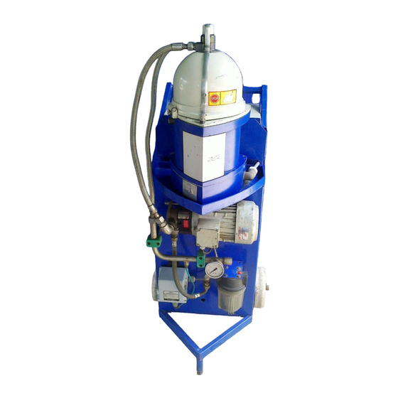
2.2 Description of main parts 2 Separator basics Description of main parts 2.2.1 Overview A general view of the separator is shown in the illustration beside. The dirty liquid is fed to the inlet (A) and down to the rotating bowl (1) where separation takes place. -
Page 17: Detailed Description
(2) are held in place by the lock nut (5). NOTE The lock nut has a conventional right-hand thread contrary to most Alfa Laval separators that have left-hand threaded lock rings. The paring disc (3) is stationary, held by the paring disc knob (1). -
Page 18: Paring Disc
2.3 Working principle 2 Separator basics 2.2.3 Paring disc The paring disc serves as a stationary pump wheel mounted in a chamber in the rotating bowl neck. The paring disc dips radial into the rotating liquid ring and pares out the liquid (coolant). The paring disc is used as a discharge pump. -
Page 19: Operating Instructions
3 Operating instructions Operating routine 3.1.1 Introduction These operating instructions describe routine procedures to follow before and during the start, running and stopping sequences of the separator. NOTE If there is a System Manual, always follow the operating instructions given therein. If there is no System Manual the instructions below are to be followed. -
Page 20: Start
3.1 Operating routine 3 Operating instructions 3.1.3 Start 1. Make sure that the outlet valve (if any) for cleaned coolant is open. 2. Start the separator (keep the button pressed 3 - 4 seconds). WARNING Disintegration hazard Some vibrations can occur for short periods during the start phase when the separator passes through the critical speed. -
Page 21: Operation
3 Operating instructions 3.1 Operating routine 3.1.4 Operation NOTE Never run the separator longer than 3 days between bowl cleaning. Check the separator for correct operation (temperature, counter pressure and vibration). This is especially important the first few times the separator is run after installation or after any dismantling and assembly has been carried out. -
Page 22: Manual Stop
3.1 Operating routine 3 Operating instructions 3.1.5 Manual stop NOTE After each stop the separator bowl must be well cleaned. Otherwise an unevenly spaced sludge cake will at next start result in heavy vibration and damage can be caused. 1. Turn off the liquid feed. 2. -
Page 23: Automatic Stop
3 Operating instructions 3.1 Operating routine 3.1.6 Automatic stop The separator is automatically stopped by the electronic safety devices if one of the following situations should occur: too high current due to overload of the separator motor too high temperature in the frequency converter ... - Page 24 3.1 Operating routine 3 Operating instructions...
-
Page 25: Trouble Shooting
4 Trouble shooting The separator does not start Possible cause Action Safety yoke is not in the correct Position the yoke correctly. position. No power supplied to the separator. Check the mains switch, fuses and supply line. Defective magnetic safety switch Make sure that the switch opens and closes when the safety indicating the position of the safety yoke is moved up and down. -
Page 26: The Separator Stops
4.2 The separator stops 4 Trouble shooting The separator stops Possible cause Action The safety yoke has been moved out Reposition the yoke. Running position = vertical. of its position. Overload due to incorrect assembly. Check the bowl assembly. Too high counter pressure. Reduce the counter pressure (100 - 200 kPa is recommended). -
Page 27: Noise
4 Trouble shooting 4.4 Noise Noise Possible cause Action Incorrect assembly. Dismantle and assemble correctly. Motor bearings are damaged. Fit new bearings. Vibration dampers are worn. Fit new dampers. Low outlet flow Possible cause Action Too low flow rate of feed. Check the feed line - increase the flow rate. -
Page 28: Some Coolant Is Escaping Through Oil Outlet
4.7 Some coolant is escaping through oil outlet 4 Trouble shooting Some coolant is escaping through oil outlet Possible cause Action Too high counter pressure at outlet. Reduce the counter pressure (100 - 200 kPa is recommended). The separator disc stack is clogged. Clean the separator bowl and disc stack.... -
Page 29: Maintenance
5 Maintenance WARNING Entrapment hazard To avoid accidental start, switch off and lock the power supply before starting any dismantling work. Make sure that rotating parts have come to a complete standstill before starting any dismantling work. Cleaning The separated sediment collected inside the separator bowl must be removed manually. -
Page 30: Once Per Year
5.2 Once per year 5 Maintenance Once per year Replace the O-rings with new ones included in the O-ring service kit. Their positions are shown in the Spare Parts Catalogue. Before fitting, lubricate the O-rings. ‘‘5.4.3 Replacement of O-rings” on page 36 how to proceed. -
Page 31: Dismantling - Assembly Instructions
5 Maintenance 5.4 Dismantling - assembly instructions Dismantling - assembly instructions 5.4.1 Introduction The illustrations on the following pages describe step by step how to dismantle, clean, replace and assemble the various parts of the separator. The illustrations have symbols only to indicate the actions required. -
Page 32: Cleaning Of Bowl
5.4 Dismantling - assembly instructions 5 Maintenance 5.4.2 Cleaning of bowl Comments to illustrations on opposite page. Illustration 4: Before dismantling the separator, wait until the rotating parts have come to a complete standstill, which will take up to two minutes. To be sure, open the front cover and check that the rotation of the electric motor shaft has stopped. - Page 33 5 Maintenance 5.4 Dismantling - assembly instructions Dismantling See comments on opposite page...
- Page 34 5.4 Dismantling - assembly instructions 5 Maintenance Comments to illustrations on opposite page. Illustration 16: When fitting the bowl wall, press firmly downwards with both hands to overcome the resistance from the O-ring fitted on the bowl bottom. A “clicking” sound will be heard. Illustration 17: If the level ring (1) and O-ring (2) have been removed, first fit the level ring and then the O-ring...
- Page 35 5 Maintenance 5.4 Dismantling - assembly instructions Illustration 22: NOTE Always screw home the knob fitted on the connecting housing before tightening the screws shown in illustration 23. Otherwise there is a risk that the pin inside the connecting housing could break.
-
Page 36: Replacement Of O-Rings
5.4 Dismantling - assembly instructions 5 Maintenance 5.4.3 Replacement of O-rings Comments to illustrations on opposite page. Illustration 5: Take care of the washer. Illustration 13: Check that the washer is fitted. Otherwise there is a risk that the bowl will not make firm contact with the spindle. - Page 37 5 Maintenance 5.4 Dismantling - assembly instructions First dismantle the separator bowl as described in ‘‘5.4.2 Cleaning of bowl” on page See comments on opposite page.
-
Page 38: Replacement Of Motor Bearings
5.4 Dismantling - assembly instructions 5 Maintenance 5.4.4 Replacement of motor bearings First dismantle the separator bowl as described in ‘‘5.4.2 Cleaning of bowl” on page... - Page 39 5 Maintenance 5.4 Dismantling - assembly instructions...
- Page 40 5.4 Dismantling - assembly instructions 5 Maintenance Assembly ‘‘ ” on page 35 for how to assemble the rest of the separator.
-
Page 41: Replacement Of Connection Housing
5 Maintenance 5.4 Dismantling - assembly instructions 5.4.5 Replacement of connection housing... - Page 42 5.4 Dismantling - assembly instructions 5 Maintenance...
-
Page 43: Technical References
6 Technical references Product description Alfa Laval ref. 576350, rev. 4 Product number: 881176-09-01/1 Separator type: IFB 403X-73 Application: Removal of solids and tramp oil from coolants Technical design: Solid-wall separator bowl made of aluminium and plastics with concentrator function. -
Page 44: Declaration
The technical construction file for the machinery is compiled and retained by the authorized person Fredrik Nytomt within the Business Unit High Speed Separators, Alfa Laval Tumba AB, SE-14780 Tumba, Sweden. By reasoned request all relevant technical documentation will be sent by post to national authorities. - Page 45 6 Technical references 6.1 Product description Signed for and on behalf of: ...................... Place: ..........................................Date of issue: Signature: ..........................................Name: ...................... Function:...
-
Page 46: Technical Data
6.2 Technical data 6 Technical references Technical data Alfa Laval ref. 576339, rev. 3 General technical data Motor power: 0,45 Power consumption, idling / at max. capacity: 0,2 / 0,5 Gear ratio: direct drive Bowl inner diameter max: Jp reduced to motor shaft:... -
Page 47: Basic Size Drawing
6 Technical references 6.3 Basic size drawing Basic size drawing Alfa Laval ref. 576171, rev. 0 All connections to be installed non-loaded and flexible... -
Page 48: Connection List
6.4 Connection list 6 Technical references Connection list Alfa Laval ref. 576334, rev. 0 Description Requirements/limits Inlet for process liquid Allowed temperature Min. 15 °C, max. +70 °C Viscosity Max. 40 cSt Flowrate Max. 525 litres/hour ... -
Page 49: Interface Description
6 Technical references 6.5 Interface description Interface description Alfa Laval ref. 576337 rev. 1 6.5.1 Scope This document gives information, requirements and recommendations about operational procedures and signal processing for safe and reliable operation of the separator. It is intended to be used for designing auxiliary equipment and control system for the separator. -
Page 50: Definitions
6.5 Interface description 6 Technical references 6.5.3 Definitions For the purpose of this document, the following definitions apply: Maximum allowed speed: The speed the separator bowl and other, to the bowl spindle attached parts, never shall exceed. Change of separator mode: It is assumed that the control system has done a reasonable amount of trials to correct the fault condition before further steps are initiated. -
Page 51: Description Of Separator Modes
6 Technical references 6.5 Interface description 6.5.5 Description of separator modes For control purposes the operation of the separator should be divided into different modes. The normally used modes are described below but other modes might exist. It is assumed that: ... -
Page 52: Handling Of Connection Interfaces
6.5 Interface description 6 Technical references STOPPING means: The power to the separator motor is off. The bowl is rotating and decelerating. STOPPING is a collective denomination for a number of sub modes which e.g. can be: NORMAL STOP: A manually or automatically initiated stop. - Page 53 6 Technical references 6.5 Interface description There shall be a start button close to the separator that shall be used for first start after assembly of the separator. Signal processing in STARTING: The separator should be stopped automatically according to NORMAL STOP procedure and an alarm should be given when the accumulated time for acceleration is longer than the maximum time specified in...
-
Page 54: Fluid Connections
6.5 Interface description 6 Technical references 6.5.7 Fluid connections Complementary information is given in "Connection List". 201 Inlet Processing in STAND STILL: Shall be closed. Processing in STARTING: Shall be closed. Bowl will be empty or filled depending on if start is done from STAND STILL or STOPPING. -
Page 55: Foundation Drawing
6 Technical references 6.6 Foundation drawing Foundation drawing Alfa Laval ref. 576170, rev. 0 Recommended free floor space Recommended thickness 3 min Horizontal deviation, max. 3° Service side 3 x Ø7 ±0,2 mm, spaced 120° for foundation bolts... -
Page 56: Plate Location Drawing
6.7 Plate location drawing 6 Technical references Plate location drawing Alfa Laval ref. 576172, rev. 0 1. Safety label Warning label placed on the separator hood. Interpretation: Stop! Read the instruction manuals before installation, operation and maintenance. Failure to strictly follow instructions can lead to fatal injury.
Need help?
Do you have a question about the IFB 403X-73 and is the answer not in the manual?
Questions and answers