
Related Manuals for Alfa Laval MBUX 510T-34C


Summary of Contents for Alfa Laval MBUX 510T-34C
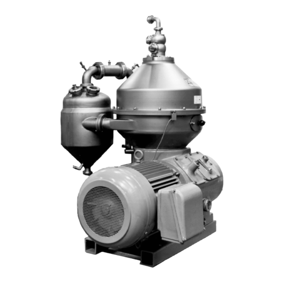
- Page 1 Instruction Manual High Speed Separator MBUX 510T-34C Product No. 881159-01-02/3 Book No. 1270176-02 Rev. 5...
- Page 2 Telefax: +46 8 530 310 40 Original instructions are in English © Alfa Laval Tumba AB 25 June 2013 This publication or any part there of may not be reproduced or transmitted by any process or means without prior written permission of...
-
Page 3: Table Of Contents
Contents Read this first Safety Instructions 2.1 Warning signs in text 2.2 Environmental issues 2.3 Requirements of personnel Separator Basics 3.1 Basic principles 3.2 Definitions 3.3 General description 3.4 Liquid flow in the bowl Operating Instructions 4.1 Operating routine 4.2 First start 4.3 Start after service 4.4 Start 4.5 Stop... - Page 4 5.9 Vibration 5.10 Common maintenance directions 5.11 General tools Dismantling/Assembly 6.1 Introduction 6.2 Feed and discharge device 6.3 Machine top part (with large cyclone) 6.4 Machine top part (with small cyclone) 6.5 Separator bowl 6.6 Machine bottom part 6.7 Vertical driving device 6.8 Horizontal driving device 6.9 Frame feet Trouble-Tracing...
- Page 5 8.13 Quality specifications 8.14 Machine plates and safety labels 8.15 Storage and installation...
- Page 7 Read and understand instruction manuals and observe the warnings before installation, operation, service and maintenance. Not following the instructions can result in serious accidents. In order to make the information clear only foreseeable conditions have been considered. No warnings are given, therefore, for situations arising from the unintended usage of the machine and its tools.
-
Page 9: Read This First
175. If the separator has been delivered and installed by Alfa Laval as part of a processing system, this manual is a part of the system documentation. In this case, study carefully all the instructions in the system documentation. - Page 10 1 Read this first Service Instructions This chapter gives instructions for daily checks, cleaning, oil changes, servicing and check points. Dismantling / Assembly This chapter contains step-by-step instructions for dismantling and assembly of the separator for service and repair. Trouble-tracing Refer to this chapter if the separator functions abnormally.
-
Page 11: Safety Instructions
Strictly follow the instructions for installation, operation and maintenance. Ensure that personnel are competent and have sufficient knowledge of maintenance and operation, especially concerning emergency stopping procedures. Use only Alfa Laval genuine spare parts and the special tools supplied. - Page 12 Use the separator only for the purpose and parameter range specified by Alfa Laval. Check that the gear ratio is correct for power frequency used. If incorrect, subsequent overspeed may result in a serious break down.
- Page 13 2 Safety Instructions Entrapment hazards Make sure that rotating parts have come to a complete standstill before starting any dismantling work. If there is no braking function the run down time can exceed two hours. To avoid accidental start, switch off and lock power supply before starting any dismantling work.
- Page 14 2 Safety Instructions Noise hazards Use ear protection in noisy environments. Burn hazards Lubrication oil, machine parts and various machine surfaces can be hot and cause burns. Wear protective gloves. Skin irritation hazards When using chemical cleaning agents, make sure you follow the general rules and suppliers recommendation regarding ventilation, personnel...
- Page 15 2 Safety Instructions Cut hazards Sharp edges, especially on bowl discs and threads can cause cuts. Wear protective gloves. Flying objects Risk for accidental release of snap rings and springs when dismantling and assembly. Wear safety goggles. Health hazard ...
-
Page 16: Warning Signs In Text
2 Safety Instructions Warning signs in text Pay attention to the safety instructions in this manual. Below are definitions of the three grades of warning signs used in the text where there is a risk for injury to personnel. DANGER Type of hazard DANGER indicates an imminently hazardous situation which, if not avoided,... -
Page 17: Environmental Issues
2 Safety Instructions Environmental issues Unpacking Packing material consists of wood, plastics, cardboard boxes and in some cases metal straps. Wood and cardboard boxes can be reused, recycled or used for energy recovery. Plastics should be recycled or burnt at a licensed waste incineration plant. -
Page 18: Requirements Of Personnel
2 Safety Instructions Requirements of personnel Only skilled or instructed persons are allowed to operate the machine, e.g. operating and maintenance staff. Skilled person: A person with technical knowledge or sufficient experience to enable him or her to perceive risks and to avoid hazards which electricity/mechanics can create. -
Page 19: Separator Basics
3 Separator Basics Contents 3.1 Basic principles 3.1.1 Factors influencing the separation result 3.2 Definitions 3.2.1 Throughput 3.2.2 Reception ability 3.2.3 Purification 3.2.4 Clarification 3.2.5 Concentration 3.2.6 Sediment/Concentrate 3.2.7 Centrate 3.3 General description 3.3.1 Machine top part with large and small cyclone 3.3.2 Bowl... -
Page 20: Basic Principles
3.1 Basic principles 3 Separator Basics Basic principles The purpose of separation can be: to free a liquid of solid particles, to separate two mutually insoluble liquids with different densities while removing any solids presents at the same time, ... -
Page 21: Factors Influencing The Separation Result
3 Separator Basics 3.1 Basic principles 3.1.1 Factors influencing the separation result Separating temperatures For some types of process liquids (e.g. mineral oils) a high separating temperature will normally increase the separation capacity. The temperature influences oil viscosity and density and should be kept constant throughout the separation. -
Page 22: Definitions
3.2 Definitions 3 Separator Basics Phase proportions An increased quantity of heavy phase in a process liquid will influence the separating result through the optimum transporting capacity of the disc stack. An increased heavy phase content can be compensated for by reducing the throughput in order to restore the optimum separating efficiency. -
Page 23: Purification
3 Separator Basics 3.2 Definitions 3.2.3 Purification A liquid separation in which the machine is used for separating two intermixed liquids, which are insoluble in each other and have different specific gravities, the lighter liquid constituting the major part of the mixture. Solids with specific gravities higher than those of the liquids can be separated off at the same time. -
Page 24: General Description
3.3 General description 3 Separator Basics General description 3.3.1 Machine top part with large and small cyclone The MBUX 510-34C separator is a high-speed centrifugal separator intended for: Biotechnical application where sterilization is needed. The separator has to be installed together with devices for control of its operation. - Page 25 3 Separator Basics 3.3 General description Paring disc Bowl Axial seal Frame hood Cyclone (small) 201. Inlet for product 222. Concentrate outlet 220. Outlet for clarified liquid 321. Washed out solids 405. Cooling water in 406. Cooling water out...
-
Page 26: Bowl
3.3 General description 3 Separator Basics 3.3.2 Bowl... - Page 27 3 Separator Basics 3.3 General description Bowl body O-ring Bushing O-ring O-ring Valve operating slide 6A. Bushing * 6B. Nozzle Compression spring * Spring support * 10. Valve plug * 11. Valve seating * 12. Guide ring 13. Screw 14. Vortex holder 15.
-
Page 28: Sediment Ejection
3.3 General description 3 Separator Basics 3.3.3 Sediment ejection Sediment ejection takes place through nine valves seats in the bowl body. Between ejections, these are kept closed by the operating slide and the valve plugs which are pressed up against the valve seats by coil springs. -
Page 29: Safety Precautions
3 Separator Basics 3.3 General description 3.3.4 Safety precautions Lock ring Tighten the large lock ring until solid contact is obtained between bowl and bowl body (ø-marks exactly in line). Use the accompanying compression tool for the disc set. Note! Do not use the compression tool as lifting tackle. - Page 30 3.3 General description 3 Separator Basics Paring disc The machine is equipped with a paring disc, for the light phase (effluent). A paring disc is a stationary pump mounted in a chamber in the rotating bowl neck. The paring disc dips radially into the rotating liquid which then is pared out.
-
Page 31: Machine Bottom Part
3 Separator Basics 3.3 General description 3.3.5 Machine bottom part Motor Frame Oil drain screw Oil gauge glass Air chamber Junction box Oil filling screw... -
Page 32: Mechanical Power Transmission
3.3 General description 3 Separator Basics 3.3.6 Mechanical power transmission The main parts of the power transmission between the motor and the bowl are: The coupling disc (F), worm gear (C, D) and bowl spindle (A). The worm gear has a ratio which increases the bowl speed several times compared with the motor speed. -
Page 33: Motor
3 Separator Basics 3.3 General description 3.3.8 Motor CT-motor (Control-Torque motor) This separator has a rigid coupling and for this reason the motor must be able to endure long run-up times. The motor supplied with the machine is of special design. -
Page 34: Revolution Counter
3.3 General description 3 Separator Basics 3.3.9 Revolution counter It is essential to operate the machine at the correct speed both in order to achieve the best separating results and for reasons of safety. Count the number of revolutions per minute, by putting a thumb against the revolution counter. -
Page 35: Liquid Flow In The Bowl
3 Separator Basics 3.4 Liquid flow in the bowl Liquid flow in the bowl Feed inlet and outlet The feed enters the bowl through the inlet pipe (A). Down under the distributor (B). The feed is accelerated by the wings under the distributor. The feed flows up through the distributing holes into the disc stack (C) where the separation takes place. -
Page 36: Self-Regulating Vortex Nozzles
3.4 Liquid flow in the bowl 3 Separator Basics Concentrate The concentrate in the solids pockets is forced through the concentrates tubes (G) and internal vortex nozzles (H) to a paring chamber where a paring tube (I) pumps the concentrate from the paring chamber to the concentrate outlet at the top of the frame hood. - Page 37 3 Separator Basics 3.4 Liquid flow in the bowl The vortex nozzle´s position in the bowl body below the concentrate paring chamber. If the solids flow in the feed increases, this is balanced by an increased flow rate out of the vortex nozzle.
- Page 38 3.4 Liquid flow in the bowl 3 Separator Basics...
-
Page 39: Operating Instructions
4 Operating Instructions Contents 4.1 Operating routine 4.1.1 Before first start 4.2 First start 4.3 Start after service 4.4 Start 4.4.1 When the separator has reached full speed 4.5 Stop 4.6 Safety stop... -
Page 40: Operating Routine
4.1 Operating routine 4 Operating Instructions Operating routine These instructions are related only to the separator itself. If the separator is a part of a system or module follow also the instructions for the system. 4.1.1 Before first start Technical demands for connections and logical limitations for the separator can be found in this chapter: ... -
Page 41: First Start
4 Operating Instructions 4.2 First start First start Cooling water must be fed to the seals during the starting and stopping periods as well as during operation. Flow data See ‘‘8.5.3 Connection list” on page 189. Open the outlet valve. Start pumps, if any. Check the safety water system. -
Page 42: Start
4.4 Start 4 Operating Instructions Start Start the separator. Be alert for unusual noises and conditions. Note the normal occurrence of critical speed periods. Some vibrations occur for short periods during the starting cycle, when the separator passes through its critical speeds. This is normal and passes over without danger. -
Page 43: Stop
4 Operating Instructions 4.5 Stop Stop Flush out the process liquid with water before stop. NOTE Turn on the water before the process liquid valve is closed. NOTE The bowl must be filled with liquid throughout the stopping period. ... -
Page 44: Safety Stop
4.6 Safety stop 4 Operating Instructions Safety stop If the separator begins to vibrate excessively during operation, stop it immediately by pushing the safety stop. The separator motor is switched off. Keep the liquid feed or safety water on during the run-down to minimize the excessive vibration. -
Page 45: Service Instructions
5 Service Instructions Contents 5.1 Periodic maintenance 5.5.2 Bowl 5.5.3 Other parts 5.1.1 Introduction 5.1.2 Maintenance intervals 5.6 Cleaning 5.1.3 Maintenance procedure 5.1.4 Service kits 5.6.1 External cleaning 5.6.2 Cleaning of bowl discs 5.2 Maintenance Logs 5.7 Cleaning program 5.2.1 Daily checks 5.2.2 Oil change... -
Page 46: Periodic Maintenance
5.1 Periodic maintenance 5 Service Instructions Periodic maintenance 5.1.1 Introduction Periodic (preventive) maintenance reduces the risk of unexpected stoppages and breakdowns. Follow the maintenance logs on the following pages in order to facilitate the periodic maintenance. WARNING Disintegration hazards Separator parts that are either worn beyond their safe limits or incorrectly assembled may cause severe damage or fatal injury. - Page 47 5 Service Instructions 5.1 Periodic maintenance Intermediate Service (IS) Intermediate Service consists of an overhaul of the separator bowl and inlet/outlet device every 3 months or 2000 operating hours. Seals in bowl and gaskets in inlet/outlet device are renewed. Major Service (MS) Major Service consists of an overhaul of the complete separator and includes an Intermediate Service every 12 months or 8000 operating...
-
Page 48: Maintenance Procedure
5.1 Periodic maintenance 5 Service Instructions 5.1.3 Maintenance procedure At each Intermediate and Major Service, take a copy of the maintenance log and use it for notations during the service. An Intermediate and Major Service should be carried out in the following manner: 1. -
Page 49: Service Kits
Service and for servicing the frame feet the Spare Parts Catalogue. NOTE Always use Alfa Laval genuine parts as otherwise the warranty will become invalid. Alfa Laval takes no responsibility for the safe operation of the equipment if non-genuine spare parts are used. WARNING Disintegration hazards Use of imitation parts may cause severe damage. -
Page 50: Maintenance Logs
5.2 Maintenance Logs 5 Service Instructions Maintenance Logs 5.2.1 Daily checks The following steps should be carried out daily. Main component and activity Part Page Notes Inlet and outlet Check for leakage Connecting housing. – Separator bowl Check for vibration and noise Horizontal driving device Worm wheel shaft and gear casing Check... -
Page 51: Oil Change
5 Service Instructions 5.2 Maintenance Logs 5.2.2 Oil change The oil change and check of worm gear should be carried out every 1000-1500 hours of operation. Note! In a new installation, or after replacement of gear, change the oil after 200 operating hours and clean the gear housing. -
Page 52: Intermediate Service (Is)
5.2 Maintenance Logs 5 Service Instructions 5.2.3 Intermediate Service (IS) Name of plant: Local identification: Separator: MBUX 510-34C Manufacture No./Year: Total running hours: Product No: 881159-01-02/2 Date: Signature: Main component and activity Part Page Notes Inlet and outlet Clean and inspect Inlet pipe –... - Page 53 5 Service Instructions 5.2 Maintenance Logs Main component and activity Part Page Notes Vertical driving device Clean and check Bowl spindle taper Horizontal driving device Worm wheel shaft and gear housing Check Worm wheel and worm Renew Oil in gear housing Oil drain plug packing –...
-
Page 54: Major Service (Ms)
5.2 Maintenance Logs 5 Service Instructions 5.2.4 Major Service (MS) Name of plant: Local identification: Separator: MBUX 510-34C Manufacture No./Year: Total running hours: Product No: 881159-01-02/2 Date: Signature: Main component and activity Part Page Notes Inlet and outlet Clean and inspect Inlet pipe –... - Page 55 5 Service Instructions 5.2 Maintenance Logs Main component and activity Part Page Notes Vertical driving device Clean and check Bowl spindle – Bowl spindle taper Buffer springs and ball bearing – housing Check Radial wobble of bowl spindle Renew Spindle bearings, O-rings and rubber buffers Horizontal driving device Worm wheel shaft and gear housing...
-
Page 56: Lubrication Of Electric Motor
5.2 Maintenance Logs 5 Service Instructions 5.2.5 Lubrication of electric motor Correct lubrication interval and recommended type of grease can be found on a plate fixed on the motor. The information can also be found in chapter Electric motor in the Installation Manual. Manual lubrication Regreasing while motor is running ... -
Page 57: Check Points At Intermediate Service (Is)
5 Service Instructions 5.3 Check points at Intermediate Service (IS) Check points at Intermediate Service (IS) 5.3.1 Height adjustment of Inlet/ Outlet device The adjustment is made by alter the number of height adjusting rings (A). During the check the large bowl lock ring must be firmly tightened and the frame hood clamped with the nuts. -
Page 58: Height Adjustment Of Machine Top Part
5.3 Check points at Intermediate Service (IS) 5 Service Instructions 5.3.2 Height adjustment of machine top part Check that the height of the ventilation plate is correct. See picture. To adjust the height, alter the number of adjustment washer. -
Page 59: Corrosion
Inspect regularly for corrosion damage. Inspect frequently if the process liquid is corrosive. Always contact your Alfa Laval representative if you suspect that the largest depth of the Main bowl parts to check for corrosion corrosion damage exceeds 1,0 mm or if cracks have been found. - Page 60 5.3 Check points at Intermediate Service (IS) 5 Service Instructions Stainless steel Stainless steel parts corrode when in contact with either chlorides or acidic solutions. Acidic solutions causes a general corrosion. The chloride corrosion is characterised by local damage such as pitting, grooves or cracks. The risk of chloride corrosion is higher if the surface is: ...
-
Page 61: Cracks
It is particularly important to inspect for cracks in rotating parts and especially the pillars between the sludge ports in the bowl wall. Always contact your Alfa Laval representative if you suspect that the largest depth of the damage exceeds 1,0 mm. Do not continue to use the separator until it has been inspected and cleared for operation by Alfa Laval. -
Page 62: Erosion
Disintegration hazard Inspect regularly for erosion damage. Inspect frequently if the process liquid is erosive. Always contact your Alfa Laval representative if the largest depth of any erosion damage exceeds 1,0 mm. Valuable information as to the nature of the damage can be recorded using photographs, plaster impressions or hammered-in lead. - Page 63 5 Service Instructions 5.3 Check points at Intermediate Service (IS) Surfaces particularly subjected to erosion are: 1. The underside of the distributor in the area of the distribution holes and wings in the area of openings of the inlet tube. 2.
-
Page 64: Disc Stack Pressure
5.3 Check points at Intermediate Service (IS) 5 Service Instructions 5.3.6 Disc stack pressure NOTE Ensure that the disc stack pressure is sufficient to maintain bowl balance. Insufficient pressure in the disc stack can cause vibration and reduce lifetime of ball bearings. - Page 65 5 Service Instructions 5.3 Check points at Intermediate Service (IS) 5. If the ø-mark is positioned more than 100 mm before the drill mark of the bowl body, one or more discs must be removed. 6. Continue with the above procedures until the right disc stack pressure has been reached.
-
Page 66: Thread Wear Of Lock Ring
5.3 Check points at Intermediate Service (IS) 5 Service Instructions If the difference between H1 and H2 is less than 2 mm, the disc stack pressure is correct. If it exceeds 2 mm, the number of discs is insufficient. Add one or more discs and repeat the above procedure until the correct disc stack pressure is obtained. -
Page 67: Worm Wheel And Worm; Wear Of Teeth67
5 Service Instructions 5.3 Check points at Intermediate Service (IS) 5. If the lock ring mark can be drawn past the bowl body –mark, punch the lock ring at the new position. This punch mark henceforth replaces the old –mark 6. -
Page 68: Lock Ring Joint
5.3 Check points at Intermediate Service (IS) 5 Service Instructions 5.3.9 Lock ring joint Impact marks and similar scores on lock ring, bowl hood or body can cause seizure damage. Check threads as well as contact and guiding surfaces (see arrow). Check parts for seizure damages by letting your fingers lightly slide over the area to be inspected. - Page 69 5 Service Instructions 5.3 Check points at Intermediate Service (IS) Emery cloth (grain size: 240) Hand drilling machine Defatting agent Fibre brush (diam. 25 mm) Brush wax (grain size: 600) Very fine-cut file (single-cut) Fibre brush (diam. 50 mm) 1. Clean threads, contact and guiding surfaces with a defatting agent, HNO3 (1/2% solution) or NaOH (1 - 2%) to absolute clean material.
- Page 70 5.3 Check points at Intermediate Service (IS) 5 Service Instructions 2. If the seizure damage is large, first use a fine and single-cut file, but moderately. Otherwise the damage may get worse. Remove the seizure damage material on top of the surface.
- Page 71 5 Service Instructions 5.3 Check points at Intermediate Service (IS) 4. Accomplish the remedying by polishing the damaged spot with the fibre brushes and brush wax. It is recommended to polish the whole area where seizure damage may occur. The polishing will smoothen out the complete damage, even in the deepest parts.
- Page 72 5.3 Check points at Intermediate Service (IS) 5 Service Instructions 7. Use a fibre brush to polish the Molykote into the surface. The black spray will look like black shoe cream well polished when right performed. Note! Never use the same brush as in previous operation.
-
Page 73: Bowl Spindle Taper
5 Service Instructions 5.3 Check points at Intermediate Service (IS) 5.3.10 Bowl spindle taper Impact marks and similar on the spindle taper may cause bad bowl run. Clean spindle taper with a suitable defatting solvent. Remove any impact marks on taper with an oil stone. -
Page 74: Check Points At Major Service (Ms)
5.4 Check points at Major Service (MS) 5 Service Instructions Check points at Major Service (MS) 5.4.1 Bowl spindle; radial wobble Excessive wobble is indicated by rough bowl running. Measure the wobble at the top of the spindle tapered end. Maximum permissible radial wobble: 0,05 mm. -
Page 75: Worm Wheel Shaft; Radial Wobble
Permissible radial wobble is maximum 0,10 mm. If the wobble is larger, the worm wheel shaft must be removed from the frame for closer examination. Get in touch with your Alfa Laval representative as the worm wheel shaft may need to be replaced. -
Page 76: Motor Shaft; Radial Wobble
Revolve the motor shaft by hand. Read the wobble on the shaft according to measurement in the figure. Maximum permissible radial wobble 0,10 mm. If the wobble is excessive, contact an Alfa Laval representative. Check the wobble as a preventive measure in connection with major service. -
Page 77: Lifting Instructions
5 Service Instructions 5.5 Lifting instructions Lifting instructions 5.5.1 Separator Before lifting the separator remove following parts. Inlet and outlet device Frame hood Motor Bowl Attach three endless slings or cables to the lifting eyes (the screws must be tightened with spanner). -
Page 78: Bowl
5.5 Lifting instructions 5 Service Instructions 5.5.2 Bowl This instruction describes how to lift a complete bowl, which normally is done only during a transport of the separator. When lifting the bowl, use the special lifting tool fastened on the bowl hood. NOTE Check that the lock ring is properly tightened. -
Page 79: Cleaning
5 Service Instructions 5.6 Cleaning Cleaning 5.6.1 External cleaning The external cleaning of the frame and motor should be restricted to brushing, sponging or wiping while the motor is running or is still hot. Never wash down a separator with a direct water stream. -
Page 80: Cleaning Of Bowl Discs
5.6 Cleaning 5 Service Instructions 5.6.2 Cleaning of bowl discs Handle the bowl discs carefully so as to avoid damage to the surfaces during cleaning. NOTE Mechanical cleaning is likely to scratch the disc surfaces causing deposits to form quicker and adhere more firmly. A gentle chemical cleaning is therefore preferable to mechanical cleaning. -
Page 81: Cleaning Program
5 Service Instructions 5.7 Cleaning program Cleaning program 5.7.1 Cleaning function The built-up of solids that are not discharged with the concentrate is greatly minimized thanks to the solids pockets machined out of the bowl wall. From there, however, the solids can easily be discharged by means of cleaning-in-place (CIP) at full speed. -
Page 82: Example Of A Relatively Complete Cip-Program
5.7 Cleaning program 5 Service Instructions 5.7.3 Example of a relatively complete CIP-program Media Temp. Reason Time No.of Disch. Notes period disch./ volume minutes period (litres) 1. Water Cold For primary Max. 5 Used water usually passes flushing to drain Water Hot/ For thermolysis... -
Page 83: When Changing Oil
5 Service Instructions 5.8 When changing oil When changing oil 5.8.1 Worm wheel and worm; wear of teeth To check at each oil change Check the teeth of both the worm wheel and worm for wear. Examine the contact surfaces and compare the tooth profiles with the ‘‘... - Page 84 5.8 When changing oil 5 Service Instructions Important! When using mineral-type oil in the worm gear housing, the presence of black deposits on the spindle parts is an indication that the oil base has deteriorated seriously or that some of the oil additives have precipitated.
- Page 85 5 Service Instructions 5.8 When changing oil Tooth appearance examples Satisfactory teeth: Uniform wear of contact surfaces. Surfaces are smooth. Good contact surfaces will form on the teeth when the gear is subjected to only moderate load during its running-in period. Satisfactory teeth Worn teeth: Permissible wear is as a rule 1/3 of the thickness...
-
Page 86: Oil Change Procedure
5.8 When changing oil 5 Service Instructions 5.8.2 Oil change procedure NOTE Before adding or renewing lubricating oil in the worm gear housing, the information concerning different oil groups, handling of oils, oil change intervals etc. given in chapter must be well ‘‘8.8 Lubricants”... -
Page 87: Vibration
5 Service Instructions 5.9 Vibration Vibration 5.9.1 Vibration analysis Excessive vibration or noise indicates that something is incorrect. Stop the separator and identify the cause. Use vibration analysis instrument to periodically check and record the level of vibration. See the illustration where to take measurements. -
Page 88: Common Maintenance Directions
The bearings used for the bowl spindle are special to withstand the speed, vibration, temperature and load characteristics of high- speed separators. Only Alfa Laval genuine spare parts should be used. Outer race A bearing that in appearance looks equivalent to... - Page 89 5 Service Instructions 5.10 Common maintenance directions Dismantling For bearings where no driving-off sleeve is included in the tool kit, remove the bearing from its seat by using a puller. If possible, let the puller engage the inner ring, then remove the bearing with a steady force until the bearing bore completely clears the entire length of the cylindrical seat.
- Page 90 5.10 Common maintenance directions 5 Service Instructions When assembling ball bearings, the bearings must be heated in oil to max. 125 °C. NOTE Heat the bearing in a clean container. Use only clean oil with a flash point above 250 °C.
- Page 91 5 Service Instructions 5.10 Common maintenance directions If necessary use a driving-on sleeve that abuts the ring which is to be assembled with an interference fit, otherwise there is a risk that the rolling elements and raceways may be damaged and premature failure may follow.
- Page 92 5.10 Common maintenance directions 5 Service Instructions...
-
Page 93: 5.10.3 Before Shutdowns
5 Service Instructions 5.10 Common maintenance directions 5.10.3 Before shutdowns Before the separator is shut-down for a period of time, the following must be carried out: Remove the bowl, according to instructions in chapter ‘‘6 Dismantling/Assembly” on page 101. NOTE The bowl must not be left on the spindle during standstill for more than one week. -
Page 94: 5.11 General Tools
5.11 General tools 5 Service Instructions 5.11 General tools Pos. / Description Application 1. Puller Ball bearing worm- wheel shaft 2. Puller Worm wheel, worm 3. Driving off-tool Top bearing 4. Dismounting tool Coupling drum 5. Torque pin Spanner cup nut 6. - Page 95 5 Service Instructions 5.11 General tools...
- Page 96 5.11 General tools 5 Service Instructions Pos. / Description Application 22. Snap ring tong (Hole) 36 mm 24. Hexagon Tubul. Cap nut Box spanner 25. Spanner Lock ring small 26. Spanner Lock ring large 27. Ring Mounting worm wheel shaft 28.
- Page 97 5 Service Instructions 5.11 General tools...
- Page 98 5.11 General tools 5 Service Instructions Pos. / Description Application Turning tool Bowl body Washer Brake pulley Compression tool Disc stack and discharge device Lifting tool WLL 0,8t Distributor support Lifting eye bolt Valve operating slide Spanner 3 mm Hex socket head key 4 mm Pin spanner Inlet-, outlet pipe...
- Page 99 5 Service Instructions 5.11 General tools...
- Page 100 5.11 General tools 5 Service Instructions...
-
Page 101: Dismantling/Assembly
6 Dismantling/Assembly Contents 6.1 Introduction 6.7 Vertical driving device 6.1.1 General directions 6.7.1 Exploded view 6.1.2 References to check points 6.7.2 Bowl Spindle 6.1.3 Tools 6.7.3 Dismantling 6.1.4 Tightening of screws 6.7.4 Assembly 6.2 Feed and discharge device 6.8 Horizontal driving device 6.2.1 Exploded views 6.8.1... -
Page 102: Introduction
6.1 Introduction 6 Dismantling/Assembly Introduction 6.1.1 General directions The separator must be dismantled regularly for cleaning and inspection. The recommended intervals are stated in chapter ‘‘5.1.2 Maintenance intervals” on page WARNING Entrapment hazard Make sure that rotating parts have come to a complete standstill before starting any dismantling work. -
Page 103: References To Check Points
6 Dismantling/Assembly 6.1 Introduction 6.1.2 References to check points In the text you will find references to the Check point instructions in chapter 5. The references appear in the text as in the following example: ✔ Check point ‘‘5.3.6 Disc stack pressure” on page In this example, look up check point Disc stack pressure in chapter 5 for further instructions. -
Page 104: Feed And Discharge Device
6.2 Feed and discharge device 6 Dismantling/Assembly Feed and discharge device 6.2.1 Exploded views Paring tube holder Collar Inlet and discharge pipe O-ring Paring disc O-ring O-ring Discharge cover Rectangular ring 10. O-ring 11. Outlet housing 12. O-ring 13. Inlet housing 14. - Page 105 6 Dismantling/Assembly 6.2 Feed and discharge device 6.2.2 Dismantling / Assembly These part are located in the bowl...
-
Page 106: Machine Top Part (With Large Cyclone)
6.3 Machine top part (with large cyclone) 6 Dismantling/Assembly Machine top part (with large cyclone) 6.3.1 Exploded views Machine top part (illustration on next page) Height adjusting ring Gasket Rectangular ring Frame top part Washer Nipple Screw Cap nut Flushing nozzle 3.1. - Page 107 6 Dismantling/Assembly 6.3 Machine top part (with large cyclone)
-
Page 108: Machine Top Part (With Small Cyclone)
6.4 Machine top part (with small cyclone) 6 Dismantling/Assembly Machine top part (with small cyclone) 6.4.1 Exploded views Machine top part (illustration on next page) Height adjusting ring Stud bolt Coupling nut Frame top part Cyclone Flushing nozzle Screw Gasket Pipe union 3.1. - Page 109 6 Dismantling/Assembly 6.4 Machine top part (with small cyclone)
-
Page 110: Dismantling
6.4 Machine top part (with small cyclone) 6 Dismantling/Assembly 6.4.2 Dismantling WARNING Entrapment hazards 1. Make sure that rotating parts have come to a complete standstill before starting any dismantling work. The revolution counter and the motor fan indicates if separator parts are rotating or not. - Page 111 6 Dismantling/Assembly 6.4 Machine top part (with small cyclone) 3. Remove inlet and outlet house by hand. 4. Remove two nuts opposite each other. Fit the lifting eyes in the threaded holes. 5. Unscrew and remove the nuts holding the frame hood and lift it off.
- Page 112 6.4 Machine top part (with small cyclone) 6 Dismantling/Assembly...
-
Page 113: Assembly
6 Dismantling/Assembly 6.4 Machine top part (with small cyclone) 6.4.3 Assembly 1. Fit the frame hood and tighten the frame hood nuts. NOTE Ensure the height of feed and discharge device is correctly adjusted. Incorrect height will cause the paring disc to scrape against the rotating bowl. -
Page 114: Separator Bowl
6.5 Separator bowl 6 Dismantling/Assembly Separator bowl 6.5.1 Exploded view... - Page 115 6 Dismantling/Assembly 6.5 Separator bowl Bowl body O-ring Bushing O-ring O-ring Valve operating slide 6A. Bushing 6B. Nozzle Compression spring Spring support 10. Valve plug 11. Valve seating 12. Guide ring 13. Screw 14. Vortex holder 15. O-ring 16. Vortex chamber 17.
-
Page 116: Tools To Be Used
6.5 Separator bowl 6 Dismantling/Assembly 6.5.2 Tools to be used OFF. B. Instruction book Bowl hood * Lock ring, small Bowl discs Paring chamber cover Bowl disc Washer Distributor * Level disc Tools - B. Instruction Book for Compression Tool Lock ring, large * Exchange necessities rebalancing... - Page 117 6 Dismantling/Assembly 6.5 Separator bowl Bushing Distributor support Valve plug Vortex holder, cover Valve slide * Vortex holder Valve seating Cap nut Tools Bowl body * Exchange necessities rebalancing...
- Page 118 6.5 Separator bowl 6 Dismantling/Assembly...
-
Page 119: Nozzles And Holders
6 Dismantling/Assembly 6.5 Separator bowl 6.5.3 Dismantling 1. Fit the tool (Tool 25) and unscrew the small lock ring, with some light blows, using a tin hammer. Left-hand thread! 2. Remove the small lock ring, the paring chamber and the level disc. 3. - Page 120 6.5 Separator bowl 6 Dismantling/Assembly 5. Fit the compressing tool through the lifting tool and thread it into the distributor. Turn the control lever to position for compression. 6. Compress the disc stack, by pumping the handle until the oil pressure is released through the relief valve, i.e when no resistance can be felt any more.
- Page 121 6 Dismantling/Assembly 6.5 Separator bowl 8. Loosen the large lock ring by hitting the spanner with a tin hammer. Left-hand thread! NOTE The large lock ring must be placed resting on a flat and horizontal surface to avoid distortion. Only slight distortion can make it impossible to refit.
- Page 122 6.5 Separator bowl 6 Dismantling/Assembly 11. Fit the special lifting tool to distributor and lift it of together with the disc stack. CAUTION Cut hazard Sharp edges on separator discs may cause cuts. 12. Lift out the collar (1). 13. Fit the special tool (T 49) to distributor support (2).
- Page 123 6 Dismantling/Assembly 6.5 Separator bowl 18. Loosen and remove the cap nut using special tool (T5 and T24). 19. Fit the combined driving-off and lifting tool (Tool 16). Use the handle of the tin hammer to drive the bowl of the spindle. Make sure that the cap nut is removed.
- Page 124 6.5 Separator bowl 6 Dismantling/Assembly 6.5.4 Dismantling / Spring support, valve operating slide 1. Fit the “bowl body turning tool” (T 43). Turn the bowl 90° and lower it on a wooden surface. WARNING Risk for squeezing 2. Fit the spindle (64) in the tapered hole in the bowl body and secure it with the washer and nut (64A).
- Page 125 6 Dismantling/Assembly 6.5 Separator bowl 5. Fit the compression tool through the sleeve and thread it into the spindle. 6. Compress the spring support. Pump with the handle until the oil pressure is released through the relief valve, i.e when no resistance can be felt any more.
-
Page 126: Exchange Of Valve Plugs
6.5 Separator bowl 6 Dismantling/Assembly 10. Fit two lifting eyes in the valve operating slide and lift it off from the bowl body. 11. Place the valve operating slide with the valve plugs facing upwards. 6.5.5 Exchange of valve plugs Disassemble the valve plug holder and the valve plug. - Page 127 6 Dismantling/Assembly 6.5 Separator bowl 6.5.6 Assembly / Spring support, valve operating slide 1. Fit the valve operating slide. The valve operating slide can only be fitted one way because of the uneven spaced guide pins. 2. Fit the springs and spring support. 3.
- Page 128 6.5 Separator bowl 6 Dismantling/Assembly 4. Compress the spring support. Pump with the handle until the oil pressure is released through the relief valve, i.e when no resistance can be felt any more. Fit and tighten the three nuts. Tightening torque 70-80 Nm (A). 5.
- Page 129 6 Dismantling/Assembly 6.5 Separator bowl 8. Lift and turn the bowl body and lower it on a wooden surface. Remove the “bowl body turning tool” (T 43).
-
Page 130: Assembly
6.5 Separator bowl 6 Dismantling/Assembly 6.5.7 Assembly ✔ Check points ‘‘5.3.3 Corrosion” on page ‘‘5.3.4 Cracks” on page ‘‘5.3.5 Erosion” on page ‘‘5.3.7 Thread wear of lock ring” on page ‘‘5.3.9 Lock ring joint” on page NOTE Ensure that the disc stack pressure is sufficient to maintain bowl balance. - Page 131 6 Dismantling/Assembly 6.5 Separator bowl 5. Fit the guide ring (6) and tighten the screws (5). 6. Fit the 9 complete vortex holders (4). 7. Fit the cover (3). 8. Fit the paring tube holder (2). 9. Fit the distributor support with the rectangular ring, use special tool (T49).
- Page 132 6.5 Separator bowl 6 Dismantling/Assembly 13. Fit the compressing tool through the lifting tool and thread it into the distributor. Turn the control lever to position 1 for compression. 14. Compress the disc stack. Pump with the handle until the oil pressure is released through the relief valve, i.e when no resistance can be felt any more.
- Page 133 6 Dismantling/Assembly 6.5 Separator bowl 17. Unscrew and remove the compressing tool. 18. Unscrew and remove the lifting tool (T17). 19. Fit washer (level ring), inlet pipe with paring disc and paring disc chamber. Note! The 142 mm washer should be used as standard.
-
Page 134: Machine Bottom Part
6.6 Machine bottom part 6 Dismantling/Assembly Machine bottom part 6.6.1 Exploded views... - Page 135 6 Dismantling/Assembly 6.6 Machine bottom part Frame bottom part Gasket Drain screw Gasket Screen Gasket Glass disc Rectangular ring Fixing plate 10. Screw 11. Driving device horizontal 12. Gasket 13. Bearing shield 13A Tolerance ring 14. Washer 15. Screw 16. Cylindrical pin 17.
- Page 136 6.6 Machine bottom part 6 Dismantling/Assembly...
- Page 137 6 Dismantling/Assembly 6.6 Machine bottom part Revolution counter Screw Washer Worm wheel guard Gasket Seal ring Revolution counter shaft Stop ring Slotted pin Bushing Plug Gasket Worm wheel guard Stop screw 10. Gear wheel 11. Taper pin...
-
Page 138: Vertical Driving Device
6.7 Vertical driving device 6 Dismantling/Assembly Vertical driving device 6.7.1 Exploded view... - Page 139 6 Dismantling/Assembly 6.7 Vertical driving device Bottom bearing housing Bottom bearing Insert sleeve Screw O-ring O-ring Screw Bowl spindle Ball bearing Ball bearing holder Rubber buffer Compression spring Top bearing support Oil fan Ball bearing holder upper Rubber buffer Top bearing cover O-ring Screw Worm...
- Page 140 6.7 Vertical driving device 6 Dismantling/Assembly 6.7.2 Bowl Spindle A = Loctite 242 Bowl spindle Ball bearing holder upper Rubber buffer Top bearing cover O-ring Screw O-ring Screw Washer...
- Page 141 6 Dismantling/Assembly 6.7 Vertical driving device Bottom bearing housing Oil fan O-ring Gasket Screw Screw – Worm Screw Support washer Screw Roller bearing Ball bearing Protecting collar Ball bearing holder Wear nut Rubber buffer O-ring Compression spring Bushing Top bearing support...
-
Page 142: Dismantling
6.7 Vertical driving device 6 Dismantling/Assembly 6.7.3 Dismantling WARNING Entrapment hazards 1. Make sure that rotating parts have come to a complete standstill before starting any dismantling work. The revolution counter and the motor fan indicates if separator parts are rotating or not. - Page 143 6 Dismantling/Assembly 6.7 Vertical driving device 3. On the horizontal driving device, loosen the screws in the clamping element uniformly and in the order shown in the figure. In the first round, do not loosen them more than 1/4 turn to avoid wryness in the clamping rings.
- Page 144 6.7 Vertical driving device 6 Dismantling/Assembly 7. Remove the three screws and remove the protecting cap. 8. Remove the O-ring and pull off the protecting collar. Note! No threads. 9. Unscrew the six screws and lift out the guard. 10. Remove the rubber ring.
- Page 145 6 Dismantling/Assembly 6.7 Vertical driving device 11. Unscrew and remove the six screws holding the vertical driving device. 12. Lift out the vertical driving device with the lifting tool (T18). Place the device horizontally on a wooden support. 13. Loosen the wear nut with a screw spanner. 14.
- Page 146 6.7 Vertical driving device 6 Dismantling/Assembly 15. Pull off the worm together with the roller bearing and the support washer. Use tool (T2), washer (T72) and a bar to stop the spindle from turning. Hit a few light blows with a hammer on the end of the screw if the worm won´t loosen.
- Page 147 6 Dismantling/Assembly 6.7 Vertical driving device 19. Remove the top bearing support and the lower rubber buffer. The lower rubber buffer is provided with springs. Lift out the spindle. Remove the bearing cover and the upper rubber buffer. 20. Ease off and remove the lower ball bearing holder by using the three screws removed in point (above).
-
Page 148: Assembly
6.7 Vertical driving device 6 Dismantling/Assembly 6.7.4 Assembly ✔ Check points ‘‘5.8.1 Worm wheel and worm; wear of teeth” on page ‘‘5.3.10 Bowl spindle taper” on page NOTE The bearings used for the bowl spindle are specifically designed to withstand the speed, vibration, temperature and load characteristics of high-speed separators. - Page 149 6 Dismantling/Assembly 6.7 Vertical driving device 3. Heat the top bearing assembly to max.125 °C and mount it on the spindle. Use the oil fan as a tool to secure the correct position of the top bearing assembly. See also ‘‘5.10.2 Ball and roller bearings”...
- Page 150 6.7 Vertical driving device 6 Dismantling/Assembly 5. Place the lower rubber buffer with its springs on the ball bearing holder. Maximum admitted indentations in the bearing holder and bearing support are 0,5 mm. A=max. 0,5 mm 6. Fit a new O-ring in the top bearing cover. Pull the top bearing support together with the top bearing cover by tightening the three screws.
- Page 151 6 Dismantling/Assembly 6.7 Vertical driving device 7. Mount the oil fan. 8. Force the worm by hand onto the lower cleaned tapered part of the bowl spindle. Note! The worm should not be heated before assembly. 9. Fit the support washer. Wipe off and oil the bearing seat before fitting the roller bearing.
- Page 152 6.7 Vertical driving device 6 Dismantling/Assembly 11. Fit the protecting collar. Use the hook spanner (T7). 12. Fasten the wear nut with a screw spanner. 13. Fit a new gasket in the frame top part. Note! The old one must be completely removed.
- Page 153 6 Dismantling/Assembly 6.7 Vertical driving device 15. Fit a new rubber ring in the frame top part. 16. Fit three guard and tighten the six screws. 17. Fit the protecting collar and the O-ring Note! The collar must rest against the thrust collar on the bowl spndle.
- Page 154 6.7 Vertical driving device 6 Dismantling/Assembly 19. Mount the hood above the top bearing. Tighten the screws. Check the height adjustment between bowl and ventilation plate see ‘‘5.3.2 Height adjustment of machine top part” on page Rotate the spindle and check for smooth run. No scrapings or other jarring sounds must be heard.
- Page 155 6 Dismantling/Assembly 6.7 Vertical driving device c. The catch of the dynamometric wrench is immediately released. Check continuously that the ring of the clamping element remains plane-parallel. ✔ Check points ‘‘5.4.1 Bowl spindle; radial wobble” on page ‘‘5.4.2 Worm wheel shaft; radial wobble” on page NOTE Spindle wobble may cause vibration and...
-
Page 156: Horizontal Driving Device
6.8 Horizontal driving device 6 Dismantling/Assembly Horizontal driving device 6.8.1 Exploded view Foundation beam Stud bolt Foundation girder Washer Washer Anchoring foot Brake pulley Adjusting washer Screw Motor adapter Elastic plate Screw Coupling disc... - Page 157 6 Dismantling/Assembly 6.8 Horizontal driving device Bearing housing 7C. Sleeve Round nut 7D. Ring Worm wheel shaft 7E. Screw Ball bearing 7F. Gear rim Round nut Clamp element Lock ring Ball bearing Worm wheel 10. Flat key 7A. Nave 11. Washer 7B.
-
Page 158: Tools
6.8 Horizontal driving device 6 Dismantling/Assembly 6.8.2 Tools Socket 30mm Loctite 242 Loctite 270 Socket 13 mm... -
Page 159: Dismantling
6 Dismantling/Assembly 6.8 Horizontal driving device 6.8.3 Dismantling WARNING Entrapment hazards 1. Make sure that rotating parts have come to a complete standstill before starting any dismantling work. The revolution counter and the motor fan indicates if separator parts are rotating or not. - Page 160 6.8 Horizontal driving device 6 Dismantling/Assembly 3. Remove the bearing shield. Ease it off by means of two of the fastening bolts. CAUTION Crush hazards The shield is quite heavy. Hold the shield firmly or use two longer screws as guide pins so as not to drop it during dismantling.
- Page 161 6 Dismantling/Assembly 6.8 Horizontal driving device 6. Loosen the clamp screws uniformly and successively around the clamping rings in the order stated. At the first round, do not loosen them more than 1/4 turn to avoid wryness in clamping rings. Do not screw out the clamp screws entirely.
- Page 162 6.8 Horizontal driving device 6 Dismantling/Assembly 14. Fit the puller tool and pull off the coupling disc. 15. Remove the lock ring on the worm wheel side using a pin spanner (T 61). Left-hand thread! 16. Knock loose the worm wheel shaft by means of a piece of wood and a tin hammer.
-
Page 163: Dismantling / Bearing Housing
6 Dismantling/Assembly 6.8 Horizontal driving device 18. Remove the ball bearing. Put some cotton twist into the tool to avoid damage to the shaft. The pressure should be applied to the inner race of the ball bearing. 6.8.4 Dismantling / Bearing housing The bearing housing should only be removed if it is necessary to renew it or when the separator is... - Page 164 6.8 Horizontal driving device 6 Dismantling/Assembly 6.8.5 Assembly / Horizontal driving device ✔ Check points ‘‘5.4.3 Motor shaft; radial wobble” on page 6.8.6 Assembly / Bearing housing 1. Apply Loctite 242 to the guide surface of the bearing housing and fit it to the frame if it has been removed.
- Page 165 6 Dismantling/Assembly 6.8 Horizontal driving device 5. Apply some Loctite 242 on the threads of the round nut. Lock the ball bearing in its position by tightening the nut. 6. Clean the ball bearing housing in the frame and oil the outer race of the ball bearing. Force the worm wheel shaft into its position in the frame so that the ball bearing enters correctly into its seat.
- Page 166 6.8 Horizontal driving device 6 Dismantling/Assembly 10. I the brake pulley has been removed, first lubricate the motor shaft with Molykote Paste 1000. Then knock the disc on to the motor shaft as far as possible using a piece of wood and a hammer.
- Page 167 6 Dismantling/Assembly 6.8 Horizontal driving device 14. When fitting a new gearing, always ensure that the new parts have the correct number of teeth. See ‘‘8.1 Product description” on page 176. WARNING Disintegration hazard Check that gear ratio is correct for power frequency used.
- Page 168 6.8 Horizontal driving device 6 Dismantling/Assembly 18. Mount the ball bearing (not heated) on the free end of the shaft. Apply the mounting tool and hit a few blows on the latter to ascertain that the bearing is in the correct position. 19.
- Page 169 6 Dismantling/Assembly 6.8 Horizontal driving device 22. Fix the worm wheel by first tightening the three clamping element A, B and C (see figure), but only so little that the clamping element sticks on to the worm wheel. Then tighten all the screws uniformly and in the order indicated in the order indicated in the figure (1-12).
-
Page 170: Frame Feet
6.9 Frame feet 6 Dismantling/Assembly Frame feet See also ‘‘8.15.4 Foundations” on page 230. Adjusting washer Anchoring foot... -
Page 171: Trouble-Tracing
7 Trouble-Tracing Contents 7.1 Mechanical faults 7.2 Concentration fault... -
Page 172: Mechanical Faults
7.1 Mechanical faults 7 Trouble-Tracing Mechanical faults Indication Cause Remedy Machine vibrates Moderate vibrations normally occur None at the critical number of revolutions during the running up and retardation periods Bowl out of balance due to: Bad Stop immediately and establish cleaning of clogged nozzles –... - Page 173 7 Trouble-Tracing 7.1 Mechanical faults Indication Cause Remedy Starting power too Ammeter reading incorrect Replace high Motor defect Exchange or repair motor Motor fault/switching from Y-D Rectify Ball bearing damaged Locate and exchange defective bearing Other machine defects See – Speed is too low Water in worm gear Condensation Drain water and change oil...
-
Page 174: Concentration Fault
7.2 Concentration fault 7 Trouble-Tracing Concentration fault Indication Cause Remedy Outgoing heavy Vortex nozzles to large Fit new vortex nozzles with smaller phase contains light hole diameter phase Closed valve or to high back Open valve pressure in light phase outlet Throughput too high Reduce feed rate Outgoing light phase... -
Page 175: Technical Reference
8 Technical Reference Contents 8.1 Product description 8.9 Other drawings 8.1.1 Directives & Standards 8.9.1 Foundation drawing 8.9.2 Interconnection diagram 8.2 Technical data 8.10 Motor specifications 8.3 Modification of BTUX to BTAX 8.10.1 Motor data, BROOKS 8.10.2 Electric motor 8.10.3 Motor data, ABB 8.4 Basic size drawing 8.10.4 Electric motor, ABB 8.4.1... -
Page 176: Product Description
8.1 Product description 8 Technical Reference Product description Alfa Laval ref. 557059, rev. 5 NOTE The separator is a component operating in an integrated system including a monitoring system. If the technical data in the system description does not agree with the technical data in this instruction manual, the data in the system description is the valid one. - Page 177 8 Technical Reference 8.1 Product description 8.1.1 Directives & Standards Alfa Laval ref. 591985, rev. 4 Declaration of Incorporation of partly completed Machinery The machinery complies with the relevant, essential health and safety requirements of: 2006/42/EC Machinery Directive To meet these requirements the following standards have been used:...
-
Page 178: Technical Data
Use the separator only for the purpose and parameters (type of liquid, rotational speed, temperature, density etc.) specified in this chapter and in the Purchase order documents. Consult your Alfa Laval representative before any changes outside these parameters are made. Product number... - Page 179 8 Technical Reference 8.2 Technical data Lubricating oil volume litres Max running time without flow: - with empty bowl/ with filled bowl 180/180 minutes Sound press level dB(A) Vibration level max. according to PF 7,1/11,2 mm/sec (new sep/sep in use) Alarm level for vibration monitor, Connection 750 mm/sec (1st/2nd)
-
Page 180: Modification Of Btux To Btax
8.3 Modification of BTUX to BTAX 8 Technical Reference Modification of BTUX to BTAX 1. Remove collar (1), paring tube holder (2) and the 9 complete wortex holders (3,4 and 5). 2. Fit concentrate tube plug (6). -
Page 181: Basic Size Drawing
8 Technical Reference 8.4 Basic size drawing Basic size drawing Alfa Laval ref. 557083/1, rev. 0 8.4.1 Separator, large cyclone Maximum horizontal displacement at the in/outlet connections during operations ±20 mm Maximum vertical displacement at the cyclone connections during operations ±10 mm Tightening torque 200 Nm Connection 222 turnable 360°... - Page 182 8.4 Basic size drawing 8 Technical Reference 8.4.2 Dimensions of connections Alfa Laval ref. 557083/2, rev. 0 Nut, DN 76 Type MV NW 65 Sight glass Nut, DN 51 Nut, DN 38 Nut, DN 51 Nut, DN 76 Data for connections see ‘‘8.4.3 Connection list”...
- Page 183 8 Technical Reference 8.4 Basic size drawing 8.4.3 Connection list Large cyclone Alfa Laval ref. 557176, rev. 3 Description Requirements / limits Inlet for product - Required inlet pressure (for water at max back pressure) Flow m Inlet pressure kPa...
- Page 184 8.4 Basic size drawing 8 Technical Reference Description Requirements / limits 306a Inlet for flushing with CIP liquid in air compensation 306b pipe (equipped with a 2 mm exchangeable nozzle.) Normally used only in the discharge sequence and/or for cleaning. - Pressure range 100 - 600 kPa - Pressure (recommended)
- Page 185 8 Technical Reference 8.4 Basic size drawing Description Requirements / limits Inlet for compressed air to valve on gas recirculation pipe - Pressure max 100 kPa Inlet for inert gas (if any) to frame top part Outlet for inert gas (if any) from frame top part Motor for separator Allowed frequency variation ±...
- Page 186 8.4 Basic size drawing 8 Technical Reference Description Requirements / limits Cover interlocking switch See interface description - Type Velocity transducer - Switch rating, resistive load max. - Switch rating, resistive load max. 12 V 75 VA 24 V 200VA 48 V 280VA 127 V...
-
Page 187: Basic Size Drawing
8 Technical Reference 8.5 Basic size drawing Basic size drawing Alfa Laval ref. 557116/1, rev. 0 8.5.1 Separator, small cyclone Maximum horizontal displacement at the in/outlet connections during operations ±20 mm Maximum vertical displacement at the cyclone connections during operations ±10 mm Tightening torque 200 Nm Connection 222 turnable 360°... - Page 188 8.5 Basic size drawing 8 Technical Reference 8.5.2 Dimensions of connections Alfa Laval ref. 5557116/2, rev. 0 Nut, DN 38 Nut, DN 51 Data for connections see ‘‘8.5.3 Connection list” on page 189. All connections to be installed non-loaded and...
- Page 189 8 Technical Reference 8.5 Basic size drawing 8.5.3 Connection list Small cyclone Alfa Laval ref. 557177, rev. 3 Description Requirements / limits Inlet for product - Required inlet pressure (for water at max back pressure) Flow m Inlet pressure kPa...
- Page 190 8.5 Basic size drawing 8 Technical Reference Description Requirements / limits Outlet for solid phase - Discharge frequency Max 60 discharge/h The outlet from the cyclone must always be arranged to prevent the cyclone from being filled up with sludge. Solids are discharge by gravity.
- Page 191 8 Technical Reference 8.5 Basic size drawing Description Requirements / limits Pneumatic discharge valve See interface description -Type 3-way(3/2)direct activated - Protecting class EEx ed 11 CT 74 - Degree of protection IP 65 - Power supply AC 50/60 Hz 24 V 48 V 110 V...
-
Page 192: Interface Description
8.6 Interface description 8 Technical Reference Interface description Alfa Laval ref. 557257, rev. 3 8.6.1 General In addition to the Connection List this document describes limitations and conditions for safe control, monitoring and reliable operation. At the end of the document a function graph and running limitations are found. - Page 193 8 Technical Reference 8.6 Interface description Safety stop means The machine must be stopped in the quickest and safest way because the vibration level is too high. Comply to following conditions: The bowl must be kept filled. Sludge ejection must not be made. ...
- Page 194 8.6 Interface description 8 Technical Reference Motor Temperature Sensor 730 The separator motor is equipped with three thermistor sensors, one in each winding. The sensors are connected in series and should be connected to a thermistor relay that trips the starting equipment when the temperature exceeds the tripping level, stated in ‘‘8.5.3...
- Page 195 8 Technical Reference 8.6 Interface description Speed signal during normal operation: Normal operation condition is considered to have been achieved 1 minute after D-turnover. During normal operation the speed is allowed to vary within speed limits specified below: When the synchronous speed exceeds more than 5%, the machine must be stopped and a high speed alarm must be given.
- Page 196 8.6 Interface description 8 Technical Reference Vibration signal during normal operation: Two levels of vibration are considered for this machine: a. In case of a signal exceeding set point for warning during 3 seconds: A warning alarm shall be given. The machine shall be stopped manually with a normal stop sequence and the reason of the vibration investigated.
- Page 197 8 Technical Reference 8.6 Interface description Signal processing: The circuit is closed when the frame hood of the separator is closed. The interlocking switch should be connected so that starting of the motor is prevented when the separator hood is not closed. 8.6.5 Function graph and running limitations...
-
Page 198: Paring Disc Characteristics
8.7 Paring disc characteristics 8 Technical Reference Paring disc characteristics Paring disc diameter 124 mm, 2 channels, wing height 5 mm, no level disc, only the washer. Back pressure (bar) Q (m – Maximum pressure before overflow – Airfree effluent outlet –... - Page 199 8 Technical Reference 8.7 Paring disc characteristics Paring disc diameter 124 mm,2 channels, wing height 5 mm, level disc ø 100 mm. Back pressure (bar) Q (m – Maximum pressure before overflow – Airfree effluent outlet – Inlet pressure...
- Page 200 8.7 Paring disc characteristics 8 Technical Reference Paring disc diameter 124 mm, 2 channels, wing height 5 mm, level disc ø 110 mm. Back pressure (bar) Q (m – Maximum pressure before overflow – Inlet pressure...
-
Page 201: Lubricants
8 Technical Reference 8.8 Lubricants Lubricants 8.8.1 Introduction The machine is delivered without oil in the worm gear housing. It must not be started unless oil in the quantity and of the quality prescribed has been supplied. A change of the separating temperature can make it necessary to replace the oil by oil of a different type. - Page 202 8.8 Lubricants 8 Technical Reference 8.8.2 Lubrication chart Alfa Laval ref. 55 32 16 - 01,rev. 8 Lubricating points Type of lubricant Interval The oil bath: Recommended Oil Change: Bowl spindle bearings are lubricants. lubricated by oil splash from Volume: see ‘‘Technical 1.
- Page 203 8 Technical Reference 8.8 Lubricants 8.8.3 Recommended lubricants Alfa Laval ref. 55 32 17 - 01, rev. 12 Lubricant recommendation for hygienic and non-hygienic applications Lubricants with a Alfa Laval part number are approved and recommended for use. The data in the below tables is based on supplier information in regards to lubrication properties.
- Page 204 8.8 Lubricants 8 Technical Reference Paste for assembly of metallic parts, hygienic applications (NSF registered H1 is preferred) Part No Quantity Designation Manufacturer Remark Molykote D paste Dow Corning 537086-07 50 g Molykote P-1900 Dow Corning NSF Registered H1 (22 Jan 2004) Molykote TP 42 Dow Corning 561764-01...
- Page 205 8 Technical Reference 8.8 Lubricants Silicone grease/oil for rubber rings, hygienic and non-hygienic applications Part No Quantity Designation Manufacturer Remark No-Tox Food Grade Bel-Ray NSF Registered H1 Silicone grease (16 December 2011) Dow Corning 360 Medical Dow Corning Tested according to and Fluid complies with all National Formulary (NF)
- Page 206 8.8 Lubricants 8 Technical Reference Always follow the lubrication recommendations of the bearing manufacturer. Grease for ball and roller bearings in electric motors Part No Quantity Designation Manufacturer Remark Energrease LS2 Energrease LS-EP2 Energrease MP-MG2 APS 2 Castrol Spheerol EPL 2 Castrol Multifak EP2 Chevron...
- Page 207 8 Technical Reference 8.8 Lubricants 8.8.4 Recommended oil brands Alfa Laval ref. 55 32 18 - 07, rev. 3 Paraffinic mineral lubricating oil, category (ISO-L-) CKE 320. NOTE The following is a list of recommended oil brands. Trade names and designations might vary from country to country.
- Page 208 8 Technical Reference 8.8.5 Recommended oil brands Alfa Laval ref. 55 32 19 -08, rev. 0 One group of lubricating oils is approved for this separator. It is designated as lubricating oil group B. The numerical value after the letter states the viscosity grade.
-
Page 209: Other Drawings
8 Technical Reference 8.9 Other drawings Other drawings 8.9.1 Foundation drawing Alfa Laval ref. 9008980, rev. 0 Min.lifting capacity required when doing service, Recommended free floor space for 1000 kg unloading when doing service Max. height of largest component incl. lifting tool... - Page 210 8.9 Other drawings 8 Technical Reference 8.9.2 Interconnection diagram Alfa Laval ref. 576899 rev. 1 Wire colour codes Junctions box Black White 712. Solenoid valve (pneumatic discharge) Brown 741. Speed sensor (motor shaft speed) 750. Vibration sensor Blue SHI. Shield 760.
-
Page 211: 8.10 Motor Specifications
8 Technical Reference 8.10 Motor specifications 8.10 Motor specifications 8.10.1 Motor data, BROOKS Alfa Laval ref. 551392, rev. 2 ––––– Measured (440 V, 60 Hz) Calculated Motor speed (r/min) Power output (kW) Current (A) Slip (%) Time (min) Motor speed (r/min) Cos... - Page 212 8.10 Motor specifications 8 Technical Reference Article Output Manu- Type Number Speed Speed Power Starting (kW) facturer of poles 50 Hz 60 Hz factor torque (r/min) (r/min) (cos (Nm) 545151 BROOKS UD 225 MD 1470 92,7 0,86 Motor data from BROOK test certificate X911280, 83.05.16 ...
- Page 213 8 Technical Reference 8.10 Motor specifications 8.10.2 Electric motor Alfa Laval ref. 545151, rev. 4 Plate with relubrication information M10 earth terminal 8 holes Ø 19 Cable entries tapped 2xPG42 + 1xPG13,5 Shaft dimensions Type of mounting Degree of protection...
- Page 214 IM 3001 temp. max. 40 r/min D-end N-end D-end N-end 1500 19800 26300 Esso unirex N3 IM 3001 1800 15000 2200 Any compatible grease would be suitable NOTE For complete information about motor variants, please contact your Alfa Laval representative.
- Page 215 8 Technical Reference 8.10 Motor specifications 8.10.3 Motor data, ABB Alfa Laval ref. 550695, rev. 1 ––––– Measured (440 V, 60 Hz) Calculated Current (A) Power input (A and kW) Motor speed (r/min) Time (min) Cos Motor speed (r/min) Power input (A) ...
- Page 216 8.10 Motor specifications 8 Technical Reference Article Output Manu- Type Number Speed Speed Power Starting (kW) facturer of poles 50 Hz 60 Hz factor torque (r/min) (r/min) (cos (Nm) 544726 Strömberg HXUR/E 1470 1764 0,84 455G2 B5 Motor data from Strömbergs type test. ...
- Page 217 8 Technical Reference 8.10 Motor specifications 8.10.4 Electric motor, ABB Alfa Laval ref. 544726, rev. 5 Extra large terminal box with flange FL21 with 2xM63 + 1xM16 Shaft dimensions Drain holes with closable plastic plugs (IP55 with open plugs). For horizontal mounting IM 3001, the motor has to be mounted with drain holes facing downwards.
- Page 218 LUBRICATE at first start 12 month until grease is forced out 24 h 12 month of the outlet. Clean the nipples! Any compatible grease would be suitable NOTE For complete information about motor variants, please contact your Alfa Laval representative.
-
Page 219: 8.11 Cover Interlocking Kit
8 Technical Reference 8.11 Cover interlocking kit 8.11 Cover interlocking kit Alfa Laval ref. 554796, rev. 0 Switch actuator Protective tube Screw Screw Limit switch Tube clip Screw Shrinking tubing Shrinking tubing Cable gland... -
Page 220: 8.12 Monitoring Kit
8.12 Monitoring kit 8 Technical Reference 8.12 Monitoring kit Alfa Laval ref. 557228, rev. 1 1. Vibration sensor 2. Speed sensor... - Page 221 Poor quality of the operating water may cause erosion, corrosion and/or operating problem in the separator and must therefore be treated to meet certain demands. NOTE Alfa Laval accepts no liability for consequences arising from unsatisfactorily purified operating water supplied by the customer.
- Page 222 NOTE Alfa Laval accepts no liability for consequences arising from unsatisfactorily purified compressed air supplied by the customer. The following conditions must be fulfilled: 1.
- Page 223 8 Technical Reference 8.14 Machine plates and safety labels 8.14 Machine plates and safety labels Alfa Laval ref. 557184 rev.1 1. Machine plate Separator Manufacturing No / Year Product No Machine top part Separator Bowl Machine bottom part In and outlet device Max.
- Page 224 8.14 Machine plates and safety labels 8 Technical Reference A. Representative label Space for label indicating representative. 3. Safety label W A R N I N G Text on label: WARNING Read the instruction If excessive vibration Separator must stop manuals before occurs,...
- Page 225 8 Technical Reference 8.15 Storage and installation 8.15 Storage and installation 8.15.1 Introduction Most of the installation instructions are Specifications, which are compulsory requirements. These specifications are sometimes completed with non-compulsory Recommendations, which could improve the installation quality. Additional installation information, such as drawings, connection lists and interface description, can be found previous in this chapter.
- Page 226 8.15 Storage and installation 8 Technical Reference A separator can be delivered with different types of protection: Fixed on a pallet. The separator must be stored in a storage room well protected from mechanical damage and theft and also dry and protected from rain and humidity.
- Page 227 8 Technical Reference 8.15 Storage and installation Transport Specification During transport of the separator, the bowl must always be removed from the machine. When lifting a separator it must always be hung securely. See chapter ‘‘5.5 Lifting instructions” on page WARNING Crush hazards Use correct lifting tools and follow lifting...
- Page 228 8.15 Storage and installation 8 Technical Reference Space for separator The separator shall be placed in such a way that suitable space for maintenance and repair is obtained. Specification See chapter ‘‘8.9.1 Foundation drawing” on page 209 for the service space required with the separator installed.
- Page 229 8 Technical Reference 8.15 Storage and installation 8.15.4 Foundations WARNING Crush hazard Use correct lifting tools and follow lifting instructions. Do not work under hanging load. Specification The separator should be installed at floor level, see chapter ‘‘8.9.1 Foundation drawing” on page 209.
- Page 230 8.15 Storage and installation 8 Technical Reference...
Need help?
Do you have a question about the MBUX 510T-34C and is the answer not in the manual?
Questions and answers