
Subscribe to Our Youtube Channel
Related Manuals for MRMC Studiobot-165


Summary of Contents for MRMC Studiobot-165
- Page 1 Studiobot-165 Quick Start Guide QSG Product Code: MRMC-2139-00 Product Covered: MRMC-2011-00...
- Page 2 Studiobot-165 Quick Start Guide QSG Product Code: MRMC-2139-00 Product Covered: MRMC-2011-00 © 2021 Mark Roberts Motion Control Ltd. All rights reserved. No part of this publication may be reproduced, transmitted, or translated by any means — graphical, electronic, or mechanical — including...
-
Page 3: Table Of Contents
Installation safety ............3 Software setup ...............5 Operational safety............5 Mounting the Staubli arm.............7 Connecting the cables ............10 Starting up the Studiobot-165 system .......12 Shutting down the Studiobot system.........15 Moving the Studiobot arm by hand........16 Appendix 1 Troubleshooting............20 Typical symptoms, causes, and actions ......20 Moving the axes when the Stäubli arm hard and... - Page 4 Studiobot-165 Quick Start Guide...
-
Page 5: Chapter 1 Quick Start
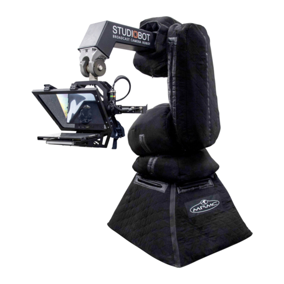
Roberts Motion Control (MRMC). Studiobot-165 is designed for reliable day-in, day-out use in professional studio broadcast environments. Studiobot-165 is equipped with a robotic arm mounted on a movable pedestal with the robot controller mounted within the pedestal. For ease of use it can be wheeled to a location of choice and then held down by four feet. -
Page 6: Safety Procedures For Using Industrial Robots
Milos. This section emphasises the safety concerns that are especially important around high-speed, high-acceleration, industrial-grade robots which can cause severe injuries, such as Studiobot-165. Unlike traditional motion control equipment, Studiobot-165 can get to maximum speed in the blink of an eye - too fast for someone to be able to quickly move out of the way. -
Page 7: Assessing A Site
Studiobot-165 Quick Start Guide Assessing a site Before setting up Studiobot-165 you need to assess the site, paying particular attention to the following points: Is the ground or floor firm enough and level enough? You might have to use boards or bricks to create a level surface. The surface needs to be strong enough to take the weight of Studiobot-165 without flexing. - Page 8 Studiobot-165 Quick Start Guide stops. Use the recommended minimum thickness steel plates. Check with MRMC if you are unsure of the exact requirements for your robot. Check that all cables are securely fixed and are not going to catch during motion.
-
Page 9: Software Setup
Have them sign the appropriate safety documents and disclaimers to ensure they understand this and are indemnifying MRMC if anything happens. Always loudly and clearly indicate to others when the rig is about to move. - Page 10 Studiobot-165 Quick Start Guide Keep the software in “slow mode” unless the move has been tested and is now specifically doing a high speed pass. In the event that a person or Actor has to be within the no-go zone during a move (hand model etc.) ensure that they fully...
-
Page 11: Mounting The Staubli Arm
Use the gantry hoist to gently lift the arm and lower it in position on the base aligning the screw slots. Tighten the four screws to secure the arm on the Studiobot-165 base. Remove the gantry hook and the straps from the arm. - Page 12 Studiobot-165 Quick Start Guide Wheel the Studiobot to the location and lower the 4 x feet to secure to the ground. Locknut Once in place, ensure that you fully secure the feet by tightening the locknut in the feet.
- Page 13 Studiobot-165 Quick Start Guide Notes...
-
Page 14: Connecting The Cables
Studiobot-165 Quick Start Guide Connecting the cables Brake Release Plug Ethernet for the Camera Cable can use or wrap bypass the J1201 Ethernet hubs in the system ETH* ETH* ONLY ETH* ROBOT TEACH VIDEO 2 VIDEO 1 E-STOP PENDANT 415 Volt... - Page 15 Studiobot-165 Quick Start Guide 24V IN Power Supply: 120-240 Volts Ethernet ETHERNET E-STOP ROBOT ONLY E-STOP POWER Power Supply: 415 Volt, 3-phase, 5-wire including VIDEO SIGNALS Neutral and Ground...
-
Page 16: Starting Up The Studiobot-165 System
Make sure you have secured the area around Studiobot-165. Release the E-stop on the Studiobot-165 base by turning the red button clockwise until the button pops up. Also make sure the key is in the clockwise position. Do not release the other E-stop by the computer stack yet. - Page 17 Power up the Robocam Atelier computer system and all of its components, including the RT-14 interface box. You can do this while the Studiobot-165 is powering up (step 3). Do not start the Robocam Atelier application yet. After Studiobot has finished powering up (step 3) and the Stäubli CS8 is displaying an “A”, check that the cifX boards in both the...
- Page 18 Studiobot-165 Quick Start Guide 10. In Robocam Atelier, move the Studiobot arm to its home position (rotated straight forward and tucked under). Hint If the Studiobot arm is in a backward or reversed starting position, the arm might swing overhead...
-
Page 19: Shutting Down The Studiobot System
Studiobot-165 Quick Start Guide Shutting down the Studiobot system Move Studiobot-165 to its Home position. or... If you are going to transport the robot to a new location, put the Studiobot arm into its transport position. You can do this either by... -
Page 20: Moving The Studiobot Arm By Hand
Studiobot-165 Quick Start Guide Moving the Studiobot arm by hand In some circumstance you need to move the Studiobot arm manually with your own hands. For example: • Recovering from a software lock-up. For example if momentum has carried the arm outside the soft limits, the software might refuse to move the arm to get back inside the limits. - Page 21 Studiobot-165 Quick Start Guide Make sure that Studiobot itself has power and is switched on. The brakes are on when the unit is switched off, so if you want to move the arm by hand, Studiobot must have power and be switched on.
- Page 22 Studiobot-165 Quick Start Guide Notes...
- Page 23 Studiobot-165 Quick Start Guide Notes...
-
Page 24: Appendix 1 Troubleshooting
The Stäubli teach pendant should only be used for troubleshooting purposes and should not be used for normal operation of the rig. The teach pendant is not related to Robocam Atelier in any way and is not an interlace to MRMC Studiobot system. Symptoms Cause and/or action Robocam Atelier fails Try a different cable. -
Page 25: Moving The Axes When The Stäubli Arm Hard And Soft Limits Are Hit
Studiobot-165 Quick Start Guide Symptoms Cause and/or action Studiobot won’t move Make sure you have enabled Studiobot in Robocam Atelier. The Staubli arm has its own hard limits for rotate, lift and arm. If any of the axes in the arm have hit the internal limits then the arm will ‘lock up’... - Page 26 Studiobot-165 Quick Start Guide Press the Power (green) button.You should hear the robot engage and the light on the arm should come on. Select Joint in the Move mode. The light on it comes on. Press the button, + or -, to take the axis back to the required position.
- Page 27 Studiobot-165 Quick Start Guide Notes...
-
Page 28: Appendix 2 Studiobot Panels
Studiobot-165 Quick Start Guide Appendix 2 Studiobot panels Studiobot-165 Quick Start Guide Studiobot-165 Quick Start Guide Studiobot base panel connector summary 1-4. ETHERNET connectors for communications between multiple Ethernet devices on the rig. These four connectors service the devices mounted on the arm via the umbilical cable wrap from base to the arm. -
Page 29: Ulti-Box Connector Summary
Ulti-box connector summary The Ulti-box that is mounted on the Bolt X arm is a multi-purpose interface box that is used to control servo motors on many MRMC heads and Lens Control Motor (LCM) units. The Ulti-box offers versatile connections for many camera and lens configurations although some of the axes connectors such as PAN, TILT, and DATA are not ordinarily used in the context of Bolt X, as Bolt X itself provides these features. - Page 30 Studiobot-165 Quick Start Guide PAN connector for the Pan servo motor on a head. For pin-out information see Servo motor connector on page 28. PROG serial connector for connection to a controller using a Serial RS232 connection (as an alternative to an Ethernet or DataLink connection), and for updating the firmware in the Ulti-box.
- Page 31 Studiobot-165 Quick Start Guide can be connected to the external E-Stop box, but if no external E-Stop is needed, a bypass jumper may be used. CAN connector is used to communicate with external CAN capable motor drives. 10,11. ZOOM, FOCUS connectors for external servo Lens Control Motors (LCMs) mounted on the camera platform.
-
Page 32: Ulti-Box Connector Pin-Out Information
Studiobot-165 Quick Start Guide Ulti-box connector pin-out information Servo motor connector This type of connector is used for six servo motor connectors on the Ulti-box: Pan, Zoom, Focus, Tilt, Aux-1, Aux-2. DATUM MOTOR_B MOTOR_A LIMIT 10. GND Program serial connector Serial connector for connection to a controller using a Serial RS232 connection, and for updating the firmware in the Ulti-box. -
Page 33: Power Connector
Studiobot-165 Quick Start Guide Power connector The power input connector for the Ulti-box. For usage see page 26. +35V +35V Camera Accessory connector This is a multi-purpose camera accessory connector with connections for three stepper motors, two serial lens controls, two trigger in controls, and two trigger out controls. -
Page 34: Data In Connector
Studiobot-165 Quick Start Guide Data In connector This is a DataLink In connector for connection to a controller using a DataLink connection. DataLink In (Up Link) connector for connection to a DataLink device higher up in the DataLink daisy-chain. For usage see. -
Page 35: E-Stop Connector
Studiobot-165 Quick Start Guide E-Stop connector This is a Lemo Size 1 2-way connector; external circuitry should keep the pins closed. E-STOP- E-STOP+ CAN connector This is a Lemo Size 0 3-way connector; is used to communicate with external CAN capable motor drives. - Page 36 Studiobot-165 Quick Start Guide Notes...
-
Page 37: Appendix 3 Specifications
Studiobot-165 Quick Start Guide Appendix 3 Specifications Studiobot-165 Quick Start Guide Studiobot-165 Quick Start Guide Dimensions Measurement Weight 630kg Height - maximum lens height 2.7 m Height - maximum mechanical clearance needed 3.6 m Length/width - maximum lens reach from centre 1.9 m... - Page 38 Studiobot-165 Quick Start Guide Notes...
- Page 39 Studiobot-165 Quick Start Guide Notes...
- Page 40 Mark Roberts Motion Control Ltd. Unit 3, South East Studios, Blindley Heath, Surrey RH7 6JP United Kingdom Telephone: +44 (0) 1342 838000 info@mrmoco.com www.mrmoco.com...
Need help?
Do you have a question about the Studiobot-165 and is the answer not in the manual?
Questions and answers