
Related Manuals for MRMC CINEBOT Bolt Jr+


Summary of Contents for MRMC CINEBOT Bolt Jr+
- Page 1 Bolt™ Jr+ COMPACT LIGHTWEIGHT HIGH SPEED CINEBOT™ RIG Quick Start Guide QSG Product Code: MRMC-2257-02 Products covered: MRMC-2050-00, MRMC-2073-01 CRANES AND RIGS | BROADCAST | HEADS & DSLR | PRODUCT PHOTOGRAPHY | RENTALS...
- Page 2 Bolt™ Jr+ Quick Start Guide Products covered: MRMC-2050-00, MRMC-2073-01 QSG Product Code: MRMC-2257-02 © 2020 Mark Roberts Motion Control Ltd. All rights reserved. No part of this publication may be reproduced, transmitted, or translated by any means — graphical, electronic, or mechanical — including...
-
Page 3: Table Of Contents
Bolt™ Jr+ Quick Start Guide Contents Bolt™ Jr+ Quick Start Guide Bolt™ Jr+ Quick Start Guide Chapter 1 Quick Start..............1 Overview .................1 Safety procedures for using industrial robots, including high speed track............2 Assessing a site ..............3 Installation safety ............3 Software setup ...............6 Operational safety............6 Mounting the Weight Plates (Bolt™... - Page 4 Bolt™ Jr+ Quick Start Guide Power Requirements............45...
-
Page 5: Chapter 1 Quick Start
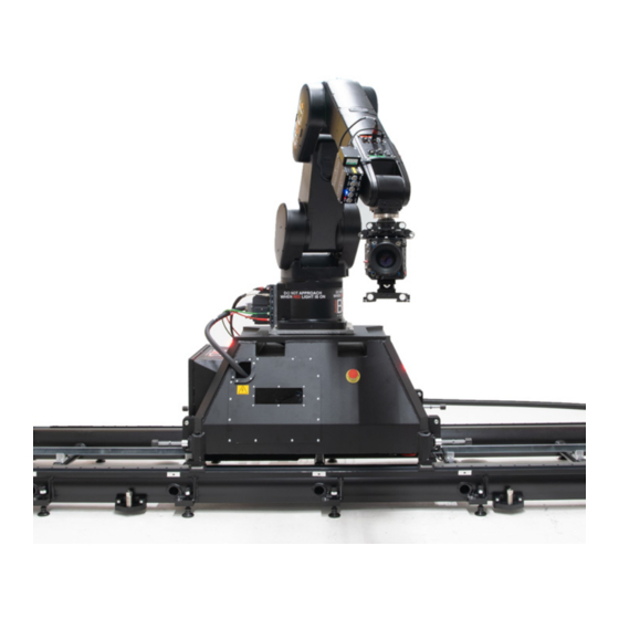
Overview Thank you for using the Bolt™ Jr+ Cinebot™ rig from Mark Roberts Motion Control (MRMC). Bolt Jr+ is designed for reliable day-in, day-out use in professional studio and Outside Broadcast environments. It has a small, lightweight robotic arm which can be used either as camera rig or model mover. -
Page 6: Safety Procedures For Using Industrial Robots, Including High Speed Track
Bolt™ Jr+ Quick Start Guide Safety procedures for using industrial robots, including high speed track Note that the words Robot and Rig are completely interchangeable and identical in meaning, for the purposes of this document. Motion Control rigs are potentially dangerous. It is important that you and everyone else on the set understand the safety notes on the following pages in order to stay safe. -
Page 7: Assessing A Site
Bolt™ Jr+ Quick Start Guide Assessing a site Before setting up Bolt Jr+ you need to assess the site, paying particular attention to the following points: Is the ground or floor firm enough and level enough? You might have to use boards or bricks to create a level surface. The surface needs to be strong enough to take the weight of Bolt Jr+ itself (390kg) plus the weight of the track (95 kg per section) or for Bolt Jr+ on Pedestal 264kg plus weights 280kg... - Page 8 Use the recommended minimum thickness steel plates. Check with MRMC if you are unsure of the exact requirements for your robot. ...
- Page 9 Bolt™ Jr+ Quick Start Guide Ideally have the robot surrounded on all four sides by a safety barrier, but where that is not practical, ensure that the maximum number of sides feasible are closed off, and that any person having to stand within reach of the robot is located as far away as possible for the shot.
-
Page 10: Software Setup
Have them sign the appropriate safety documents and disclaimers to ensure they understand this and are indemnifying MRMC if anything happens. Always loudly and clearly indicate to others when the rig is about to move. Shout “Rig Moving!” if no other means exists. - Page 11 Bolt™ Jr+ Quick Start Guide Always run any move or adjusted move slowly at first to check the motion. Even if you have checked the move previously, if you make a minor change to it then you need to recheck it. ...
-
Page 12: Mounting The Weight Plates (Bolt™ Jr+ On Pedestal)
Bolt™ Jr+ Quick Start Guide Mounting the Weight Plates (Bolt™ Jr+ on Pedestal) Bridge Line up the screw cavities Weight plate Weight box Use the jack screws on the castor wheels to lift the base high enough to insert each of the weight plates on either side of the Bolt Jr+ Base lining up the screw cavities. - Page 13 Bolt™ Jr+ Quick Start Guide Lower the base completely so it is resting on both wings. Secure the weight plates using the 2xM10 screws on either plate. The screws should be wedged to the ground to secure the weight plate completely.
- Page 14 Bolt™ Jr+ Quick Start Guide Put the weights onto the wings. Bolt Jr+ requires 2 boxes of weights — one on each side. Each box contains 140kg of weights (7 × 20kg). Hint You can use a pallet truck to move Bolt Jr+ without removing the wings and bridges if you want, as long as you take the weights off first.
-
Page 15: Mounting The Castor Wheels (Bolt™ Jr+ On Pedestal)
Bolt™ Jr+ Quick Start Guide Mounting the Castor Wheels (Bolt™ Jr+ On Pedestal) If you need to move the Bolt Jr+ on Pedestal around, use the following procedure to mount the castor wheels: Remove the bridge plates. Slide one castor wheel into the base ensuring that edge of the plate in the wheel assembly is inserted in the slot in the base. - Page 16 Bolt™ Jr+ Quick Start Guide Note that the wedge in the castor plate should be slotted properly under the base. Similarly insert all the castors into the base ensuring the plates are inserted into the slots. Secure and tighten the castor wheels to the base and use the four jack screws to lift it off the floor (24mm socket/wrench).
- Page 17 Bolt™ Jr+ Quick Start Guide Notes...
-
Page 18: Mounting The Optional Riser(S)
Bolt™ Jr+ Quick Start Guide Mounting the Optional Riser(s) Bolt Jr+ can include optional risers if higher arm reach is required. These come in two sizes: 150mm and 300mm; either or both of them can be used. Use the following instructions to mount any riser on the pedestal: Remove the arm from the base by unscrewing the 4xM12 screws and using a gantry hoist to lift the arm. - Page 19 Bolt™ Jr+ Quick Start Guide Robot arm Mounting plate Riser Note If you are using the 300mm riser, anchor the Bolt Jr+ on Pedestal down to the floor. Refer to the next section for details. Limitations when using weights If you are using weights, reduce the top-speed by 50% when you have the 300mm riser added.
-
Page 20: Anchoring Bolt™ Jr+ On Pedestal To The Floor
Bolt™ Jr+ Quick Start Guide Anchoring Bolt™ Jr+ on Pedestal to the floor If you are setting up Bolt Jr+ on Pedestal in a permanent (or semi-permanent) location, you can anchor the pedestal to the floor as an alternative to holding it down with weights. The following procedure tells you how to anchor the pedestal to a concrete floor. - Page 21 Bolt™ Jr+ Quick Start Guide At one of the holes insert the drop-in anchor insert, threads upward, all the way to the bottom. Insert the anchor spreader tool into the drop-in anchor insert. Hit the top of the anchor spreader tool with a hammer until the anchor Anchor is fully spread in the concrete.
-
Page 22: Connecting The Cables (Bolt™ Jr+ On Pedestal)
Bolt™ Jr+ Quick Start Guide Connecting the cables (Bolt™ Jr+ on Pedestal) Robot Arm (Rear) 48V OUT CAMERA (ULTI Power ETHERNET supply) VIDEO 2 VIDEO 1 Robot Controller CR800 (Rear) Single phase AC 200 to 230V POWER... - Page 23 Bolt™ Jr+ Quick Start Guide Jumper* Jumper Safety PLC RT-14 Hand Held Box 24V IN 9-Way D-type jumper Power Supply: 120-240 Volts SAFETY PLC Controller CR800 (Front) Ethernet The Jumper* only apply Wifi when you are using the Flair PC Model Mover as a single robot system.
-
Page 24: Connecting The Cables (Bolt Jr+ On Track)
Bolt™ Jr+ Quick Start Guide Connecting the cables (Bolt Jr+ on Track) Cable wrap 48V OUT ETH* ETH* ETH* E-STOP *One Ethernet (ETH) port is for network connection to the track motor controller and to the Ulti-box for LCMs via the Single phase Mitsubishi arm. - Page 25 Bolt™ Jr+ Quick Start Guide Safety PLC Jumper* Jumper Hand Held Box RT-14 24V IN 9-Way D-type jumper Power Supply: 120-240 Volts POWER Ethernet ETHERNET Wifi Flair PC INtime dongle in USB port VIDEO SIGNALS...
- Page 26 Bolt™ Jr+ Quick Start Guide Important The Jumper* in the Safety PLC applies when using this robot as a single robot operation. For more information on using the Universal Robot system with multiple robots, refer to the Universal E-stop System Quick Start Guide. The desk top E-stop box can also be daisy-chained to multiple E-stop buttons.
-
Page 27: Bolt Jr+ Arm Connectors For Ulti-Box And Camera
Bolt™ Jr+ Quick Start Guide Bolt Jr+ arm connectors for Ulti-box and camera The connections that go through the Bolt Jr+ arm are shown below. These are for the Ulti-box mounted on the arm, and for the camera that you mount in the cage at the end of the arm. -
Page 28: Starting Up The Bolt™ Jr+ On Pedestal System
Bolt™ Jr+ Quick Start Guide Starting up the Bolt™ Jr+ on Pedestal system Once you have attached all the cables, you power up the rig by switching on the components in the order described below. Make sure you have secured the area around Bolt Jr+. Put up guard rails around Bolt Jr+ (and the track) as necessary, and tell others on the set that you are now powering up the rig. - Page 29 Bolt™ Jr+ Quick Start Guide Power Auto Error Ready Loading Flair (Flair Running Enabled) (Robot enabled) Power up the Flair computer system and all of its components, including the RT-14 interface box. You can do this while the robot is powering up (step 2).
-
Page 30: Bolt™ Jr+ Start-Up Summary
Bolt™ Jr+ Quick Start Guide Once the CR800 start-up sequence is complete, release the E-stop that is plugged into the computer stack, by turning the button clockwise until the red button pops up and then pressing the Enable button. Zero the axes as required in Flair. The Bolt Jr+ arm itself does not require zeroing but you need ENABLE button to zero other axes such as:... -
Page 31: Starting Up The Bolt™ Jr+ On Track System
Bolt™ Jr+ Quick Start Guide Starting up the Bolt™ Jr+ on Track system Once you have attached all the cables, you power up the rig by switching on the components in the order described below. Make sure you have secured the area around Bolt Jr+. Put up guard rails around Bolt Jr+ (and the track) as necessary, and tell others on the set that you are now powering up the rig. -
Page 32: Bolt™ Jr+ Start-Up Summary
Bolt™ Jr+ Quick Start Guide Once the CR800 start-up sequence is complete, release the E-stop that is plugged into the computer stack, by turning the button clockwise until the red button pops up and then pressing the Enable button. Zero the axes as required in Flair. The Bolt Jr+ arm itself does not require zeroing but you need ENABLE button to zero other axes such as:... - Page 33 Bolt™ Jr+ Quick Start Guide Release the E-stop on the computer stack In Flair: Zero the track and Lens Control Motor axes Engage Robot Home the arm, carefully 10. Set the soft limits The rig is now ready to use.
-
Page 34: Shutting Down The Bolt™ Jr+ System
Bolt™ Jr+ Quick Start Guide Shutting down the Bolt™ Jr+ system Move Bolt Jr+ to its Home position, for both the arm and the track. or... If you are going to transport Bolt Jr+ to a new location, put the Bolt Jr+ arm into its Transport position. -
Page 35: Bolt™ Jr+ Shut-Down Summary
Bolt™ Jr+ Quick Start Guide Bolt™ Jr+ shut-down summary Move Bolt Jr+ to the Home or Transport position In Flair: Disengage Robot In Flair: Toggle off the Track Press down all E-stops Close Flair Shut down Windows Switch off Bolt Jr+ Bolt Jr+ on Track Transport position: •... - Page 36 Bolt™ Jr+ Quick Start Guide Notes...
- Page 37 Bolt™ Jr+ Quick Start Guide Notes...
-
Page 38: Appendix 1 Bolt™ Jr+ Panels
Bolt™ Jr+ Quick Start Guide Appendix 1 Bolt™ Jr+ panels Bolt™ Jr+ Quick Start Guide Bolt™ Jr+ Quick Start Guide Bolt™ Jr+ Track Base panel connector summary 240V AC output, for general use by additional devices that you want to mount on the base. VIDEO 1 IN input connector for the video 1 signal from the camera. - Page 39 Bolt™ Jr+ Quick Start Guide VIDEO 1 OUT connector for the video 1 signal from the camera. This has a straight-through connection to the VIDEO 1 IN connector (2). VIDEO 2 OUT connector for the video 2 signal from the camera. This has a straight-through connection to the VIDEO 2 OUT connector (3).
-
Page 40: Ulti-Box Connector Summary
Ulti-box connector summary The Ulti-box that is mounted on the Bolt Jr+ arm is a multi-purpose interface box that is used to control servo motors on many MRMC heads and Lens Control Motor (LCM) units. The Ulti-box offers versatile connections for many camera and lens configurations although some of the axes connectors such as PAN, TILT, and DATA are not ordinarily used in the context of Bolt Jr+, as Bolt Jr+ itself provides these features. - Page 41 Bolt™ Jr+ Quick Start Guide POWER DC input for the Ulti-box and its attached devices. The standard unit uses a power input of 24-36 Volts. The high-power variant (marked HV, for High Voltage) uses 24-48 Volts. For pin-out information see Power connector on page 39. CAM ACC Camera Accessory input/output connector.
-
Page 42: Ulti-Box Connector Pin-Out Information
Bolt™ Jr+ Quick Start Guide Ulti-box connector pin-out information Servo motor connector This type of connector is used for six servo motor connectors on the Ulti-box: Pan, Zoom, Focus, Tilt, Aux-1, Aux-2. DATUM MOTOR_B MOTOR_A LIMIT 10. GND Program serial connector Serial connector for connection to a controller using a Serial RS232 connection, and for updating the firmware in the Ulti-box. -
Page 43: Power Connector
Bolt™ Jr+ Quick Start Guide Power connector The power input connector for the Ulti-box. For usage see page 37. +35V for Basic and +48V for HV +35V for Basic and +48V for HV Camera Accessory connector This is a multi-purpose camera accessory connector with connections for three stepper motors, two serial lens controls, two trigger in controls, and two trigger out controls. -
Page 44: Data In Connector
Bolt™ Jr+ Quick Start Guide Data In connector This is a DataLink In connector for connection to a controller using a DataLink connection. DataLink In (Up Link) connector for connection to a DataLink device higher up in the DataLink daisy-chain. For usage see. page 37. - Page 45 Bolt™ Jr+ Quick Start Guide Notes...
- Page 46 Bolt™ Jr+ Quick Start Guide Notes...
-
Page 47: Appendix 2 Specifications
Bolt™ Jr+ Quick Start Guide Appendix 2 Specifications Bolt™ Jr+ Quick Start Guide Bolt™ Jr+ Quick Start Guide Rig Weights Dimensions Bolt Jr+ on Track Bolt Jr+ on Pedestal Total weight 390kg 262kg Weight- Arm 132kg 132kg Weight - Base 258kg 130kg (including... -
Page 48: Rig Performance
Bolt™ Jr+ Quick Start Guide Rig Performance Axis Travel (degrees) Max Speed (degrees/s) Rotate 370(±185) Lift 230 (-55 to +175) 160 (-65 to +95) 390 (±195) Tilt 230 (-205 to +25) Roll 1420(±710) Track Unlimited 2.9 m/s Note The Roll limits can be extended further but will require caution for the external cables Operating Envelope Maximum Height (From Ground) -
Page 49: Bolt™ Base Cavities Dimension
Bolt™ Jr+ Quick Start Guide Bolt™ Base Cavities Dimension 187mm 180mm 187mm Dimensions in Transport position Bolt Jr+ on Track Width 1.5m x Depth 1.65m x Height 1.40m Power Requirements Power supply: Single phase Line+Neutral+Earth Voltage: 200-230 Volts with 10% tolerance Current: 2x16A;... - Page 50 Bolt™ Jr+ Quick Start Guide system. When using an earth-leakage current breaker as a safety device, select the product that meets the following specifications: Item Unit Specification Rated voltage AC200 to 230 Rated sensitivity current 30 or more Rated current 10 or more Bolt Jr+ on Track power requirement: 7KVA (Arm - 4KVA + Track - 3 KVA)
- Page 51 Bolt™ Jr+ Quick Start Guide Notes...
- Page 52 Mark Roberts Motion Control Ltd. Unit 3, South East Studios, Blindley Heath, Surrey RH7 6JP United Kingdom Telephone: +44 (0) 1342 838000 info@mrmoco.com www.mrmoco.com...
Need help?
Do you have a question about the CINEBOT Bolt Jr+ and is the answer not in the manual?
Questions and answers