
Related Manuals for Gecko MC-MP


Summary of Contents for Gecko MC-MP
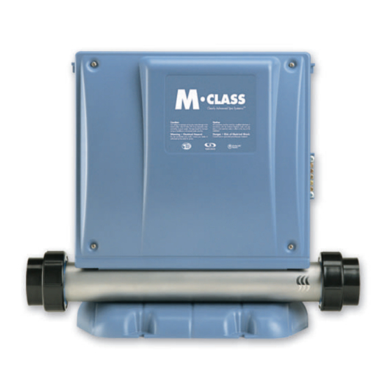
- Page 1 MC-MP SPA SYSTEMS Service Manual • by Gecko Alliance • Visual step-by-step guide to easily identify & correct technical problems!
- Page 2 Table of Contents �������������������� � ���������������� �� � ������������������ �� � ������������������������������� �� ������������ � � ����������������� �� � ���������������������� �� ���������������� � �������������������������������������������� ��� � �������������������������������� �� � �������������������� ��� � ���������������������������������������������� ��� � ���� ��� � ���� ��� �...
- Page 3 In an attempt to make this manual as useful as possible, it has been presented in two formats. Problem-solving solutions are described with Troubleshooting Flow Charts and also with Step-by-Step Procedures. The two formats together should provide an overall complete explanation, with flow charts providing an overview of specific problems, and step-by-step procedures giving more detailed information.
-
Page 4: Tools And Parts
Tools & Parts ��������������������������������������������������������� ��������������������������������� ��������������� ������ ����������������� ��� ���������������������������� ������������ ������������ ���������� ����� ����������������� ��������������������������������� ��� ����������� ��������� ����������� ����������������� ����������� ��������������� ��������������� ������������������ ����� ���������������������� ������������������������� ������������������������������������������������������������������������������������������������������������� ����������������������������������������������������������... -
Page 5: Electrical Wiring
Correct wiring of the electrical service box, GFCI box and pack terminal block is essential. Electrical Box GFCI Pack Terminal Block 1• Carry out a visual inspection to check for signs of miswiring. Refer to supplied wiring diagrams. Call an electrician if necessary. MC-MP Service Manual... - Page 6 Replace defective component. If GFCI is still tripping, disconnect There is Replace the incoming a problem GFCI. power line. with the cable. Is GFCI still tripping? Call an electrician. Replace board if GFCI is still tripping. MC-MP Service Manual...
- Page 7 4• If GFCI still trips, replace transformer. If it stops tripping, reconnect one component at a time until GFCI starts to trip. Replace defective From electrical box To spa component. 2• If it is not, verify GFCI wiring diagram and reconnect it. MC-MP Service Manual...
- Page 8 If GFCI still trips, there must be a cable problem. Call an electrician! 2• If GFCI stops tripping, replace GFCI. 3• If GFCI trips again, replace board. (Refer to "How to Replace the Board" section of this manual.) MC-MP Service Manual...
-
Page 9: Jumper Positions
Certain MC-MP spa pack parameters can be modified by changing the position of jumpers on the board. Remove MC-MP power box cover to access jumpers. (See "How to Replace the Board" section of this manual). Jumper functions may differ from information below. Please check wiring diagram on inside pack cover to verify specific functions for our pack. -
Page 10: Low Level Programming
� � �� � ������������������� � � �� � ������������������������������ � � �� � � ����������������������� � � �� � ����������������������������� � � �� � � ���������������������� � � �� � ������������������������������ � � �� � � ������������������� MC-MP Service Manual... - Page 11 MC-MP Service Manual...
- Page 12 Clear any air locks. Verify water valves. Replace pressure switch if problem persists. Replace pressure switch cable. If problem persists, replace board. Try to adjust pressure switch. If problem persists, replace board. Replace pressure switch if problem persists. MC-MP Service Manual...
- Page 13 5• If you do not detect continuity, verify if pressure switch cable is 4• If you detect continuity, go to properly connected to pressure step #10. switch and board. MC-MP Service Manual...
- Page 14 Remove plastic cover and replace (Refer to "How to Adjust the cable. Pressure Switch" section of this manual.) 9• Replace board if error condition still persists. (Refer to "How to Replace the Board" section.) MC-MP Service Manual...
- Page 15 If error condition disappears, ad- Replace the Board" section of this just pressure switch, if it is a new manual.) installation (less than two years) or replace it. (Refer to "How to Adjust the Pressure Switch" section of this manual.) MC-MP Service Manual...
- Page 16 ����������������������������������� ��� �� ���������� ��������� ����������������� ����������������� ����������� ����������������� ������������������ ����������� ���������������� ������������������� �������������������� ������������������� ��������������� ��������������������� ��������������������� �������� ��������������� ������������� ������������ ������������������ ����������������������� ������������������ ��������� ����������������� ������������������������ ���������������������� ������������������������ �������������������� ������������������ ������� �������� ����� ��������� ��������������� MC-MP Service Manual...
- Page 17 (closed valves or dirty filter). temperature. b- If it's not, verify if hi-limit probe is properly connected. Try to clean probe connector pins. Even a small coating of film can cause a bad connection. Reconnect probe and reset breaker. MC-MP Service Manual...
- Page 18 2• Make sure temperature probe is properly connected. If it is, replace probe and reset breaker. 3• Replace board if error condition still persists. (Refer to "How to Replace the Board" section of this manual.) MC-MP Service Manual...
- Page 19 MC-MP Service Manual...
- Page 20 "Heater" indicator spa cools filter cycle. on keypad display down (add should disappear. cold water Lower if needed). filter cycle Do you get a duration. 240 VAC reading between two heater wires on the board? MC-MP Service Manual...
- Page 21 � �������������������������� � ����������������������������� � ������������������������������ � ������������������������������ � �������������� ������������������������������� ��� �������������������������������� � ��������������������������������� � ���������������������������������� � ������ � ����������������������������� � ������������������������������� ��� ����������������������������� � ������������������ � ����������������������������������� � �������������������� ��� ������������������������������ � ������������������������������� � ���������������������������������� MC-MP Service Manual...
- Page 22 2• Make sure temperature probe is properly connected. If it is, replace probe. 3• Replace board if display is still flashing. (Refer to "How to Replace the Board" section of this manual.) MC-MP Service Manual...
- Page 23 MC-MP Service Manual...
- Page 24 (even a small coating of film may cause a bad connection). Reconnect the probe. Replace probe with a spare and verify if problem is solved. If it is, replace probe with spare. Replace board if problem persists. MC-MP Service Manual...
- Page 25 1• Verify if regulation probe (sensor located in spa) is properly 4• Replace board if problem connected. persists. 2• Disconnect probe connector and clean probe connector pins. Even a small coating of film may cause a bad connection. MC-MP Service Manual...
- Page 26 Ensure flow of water through heater and short two pressure Is it a new switch terminals with a jumper. Replace installation board. (less than Does FLO two years)? error condition persist? Replace pressure switch. Adjust pressure switch. MC-MP Service Manual...
-
Page 27: Flo Error Condition
(See Jumper Section). 3• Clean filter and check for air blockages, closed trap valves or anything that could be restricting 4• Verify if pressure switch cable is water flow. properly connected to pressure switch and board. MC-MP Service Manual... - Page 28 (Refer to "How to Adjust the Pressure Switch" section of this Remove plastic cover and replace manual.) cable. 8• Replace board if FLO error condition still persists. (Refer to "How to Replace the Board" section.) MC-MP Service Manual...
- Page 29 MC-MP Service Manual...
- Page 30 Is it a new Replace installation pressure (less than switch cable. two years)? Adjust Replace pressure pressure switch. switch. Replace board. Replace pressure switch if FLC error condition persists when you start or stop pump. MC-MP Service Manual...
- Page 31 2• If FLO error condition occurs when manual.) pump is started, adjust pressure switch, if it is a new installation (less than two years) or replace it. (Refer to "How to Adjust the Pres- sure Switch" section of this manual.) MC-MP Service Manual...
- Page 32 (even a small coating of film may cause a bad connection). Reconnect the probe. Replace probe with a spare and verify if problem is solved. If it is, replace probe with spare. Replace board if problem persists. MC-MP Service Manual...
-
Page 33: Prr Error Condition
1• Verify if regulation probe (sensor located in spa) is properly 4• Replace board if problem persists. connected. 2• Disconnect probe connector and clean probe connector pins. Even a small coating of film may cause a bad connection. MC-MP Service Manual... - Page 34 HL (OH) Flow Chart If HL (OH) error condition occurs (potential Hi-Limit sensor or temperature probe problem), follow Troubleshooting Flow Chart below to identify the problem: Steady message: The system has shut down because the temperature at the heater has reached 119°F (48°C). Blinking message or OH: Except for the Smart Winter Mode, the system has shut down because the water temperature in the spa has reached 112°F (44°C).
- Page 35 Proceed to page 36 if display doesn't show correct tem- perature. Try to clean probe connector pins. Even a small coating of film can cause a bad connection. Recon- nect probe and reset breaker. MC-MP Service Manual...
- Page 36 ��� ������������������������������������������������������������������������� � ������������������������������������������������������������������ ������������������������������� ��� �������������������������������� � ������������������������������� � ������������� ��� ����������������������������� � ������������������ � ����������������������������� � ������������������������������ � �������������������������� � ������������������������������ ��� ������������������������������� � �������������������������������� � ����������������������������������� ��� ������������������������������� � ����������������������������� � ���������������������������� � ������������� MC-MP Service Manual...
- Page 37 2• Make sure temperature probe is properly connected. If it is, replace probe and reset breaker. 3• Replace board if HL (OH) error condition still persists. (Refer to "How to Replace the Board" section of this manual.) MC-MP Service Manual...
- Page 38 Troubleshooting Flow Chart to identify the problem: Is the water temperature of the spa lower than the desired temperature? Do you read 240 VAC to the heater? Refer to "Spa not heating" section. System works fine. MC-MP Service Manual...
-
Page 39: Smart Winter Mode
Smart Winter Mode ����������������������������������������������������������������������� ������������������������������������������������������������������������ ��������������������������������������������������� �������������������������������������������������������������������������������������������������� ���������������������������������������������������������������������������������������� ������������������������������������������������������������������������������������������������ �������������������������� ��� ���������������������������������� � ����������������������������� ��� �������������������������������������� � ������������������������������������ � ���������������������� � ������������������������������������ � �������������������������������������� � ������������������������������������� � �������������������������������������� � ������� MC-MP Service Manual... - Page 40 If nothing still works, clean the transformer orange connector pins (even a small coating of film may cause a bad connection). Replace transformer if problem persists. Replace board if problem still persists. MC-MP Service Manual...
-
Page 41: Nothing Seems To Work
You should get ≈120 VAC. You should get ≈240 VAC. 4• If you do not get good readings, this indicates an electrical wiring problem. Call an electrician! 2• Measure voltage between line 1 and neutral. You should get ≈120 VAC. MC-MP Service Manual... - Page 42 4• Replace transformer if problem 2• Replace transformer fuse persists. if nothing still seems to work. 5• If problem is still not solved, replace board. (Refer to "How to Replace the Board" section.) MC-MP Service Manual...
- Page 43 MC-MP Service Manual...
- Page 44 ���������������� ��������������������� ���������� ������ ����������� ������������� ���������������� ������� ������ �������������� �������������������� ��� �� ��������������� ������������������ ��� ������������ ��������������� ��������� ���������������� ��������� ������ �������� ��� �� ������� ����������������� �������������������� ����������� ����������������������� ������� ������������������ ������� ������� �������� ������� ������ MC-MP Service Manual...
-
Page 45: Spa Not Heating
��� ���������������������������������� � ����������������������������������� � ����������������������������� � ����������������������������� ���� ������ ���� �������������������������������������� � ���������� �������� ��������� ��� ��������������������������������� � ����������������� ��� ������������������������������������ � ���������������� ��� ������������������������������������ � ���������� � ����������������������������������� � ���������������������������������������� � ���������������������������������� � ������������������������������������� � �������������������������� MC-MP Service Manual... - Page 46 Spa Not Heating! ���������������������������������������������������������������������������� ����������������������������������������������������� ����������������������������������������������� ��� ������������������������������������� ��� �������������������������������� � ��������������������������������� � ��������������������������������� � ������������� � ���������������������� � ���������������������������������� � ������������������������������������ � �������� � ��������������������� ��� �������������������������������� � �������� MC-MP Service Manual...
- Page 47 MC-MP Service Manual...
- Page 48 ��������� ������������������� ��������� ���������������������������� �������������� ������������������������ �������� ��������������� ����������� ��������������� ��� �� ��������������������� �������������� ������������� ���������������� ������ ��������� ������������ ��� �� ����������������� ������������ �������������������������� ������� ��� �� ������� ��������������� ����������������������������� ������������������ ����������� ������������ �������������� ������� ���������� ������ MC-MP Service Manual...
- Page 49 ��� ������������������������������ ��� ������������������������������� � ����������������������������� � �������������������������������� � ������������������������������ � ����������������������������������� � ���������� � ������������������������� � ���������������������� ��� ������������������������������������ � �������������������������������� � ����������� ��� �������������������������������� � ������������������������������ � �������������������������������������� � ���������������������������������� � ��������������������������������� � ��������������������� � ������������������������ MC-MP Service Manual...
- Page 50 240 VAC pump: P57 & P64 120 VAC pump: P48 & P64 The reading shoud be: ≈240 VAC for a 240 VAC pump ≈120 VAC for a 120 VAC pump MC-MP Service Manual...
- Page 51 ��� �������������������������������� ��� ������������������������������ � ����������������������������������� � ����������������������������� � ������������������������������������ � ���������������������������������� � ���������������� � ������������������������� ��� ������������������������������������ � ���������������������� � �������������������������������� � ����������� ��� �������������������������������� � ���������������������������������� � ��������������������������������� � ��������������������������������� � ���������������������������������� � ������������������������������ � ������ MC-MP Service Manual...
- Page 52 240 VAC pump: P58 & P35 120 VAC pump: P45 & P35 The reading shoud be: ≈240 VAC for a 240 VAC pump ≈120 VAC for a120 VAC pump MC-MP Service Manual...
- Page 53 MC-MP Service Manual...
- Page 54 ������ ������� ���� ������� ����������� �������������� ������������������������ ��������� ��������� ��������� ������� ���������������� ������ ��� �� ���� �������������� ������������������� ������������� ������������� ������� ����������� ����������� ������� ���������� ������� �������������� ������ ����������������� ����� ����������������� ����������������� ���������������� ������������� ��������� ���������� ���������� MC-MP Service Manual...
- Page 55 Blower Does Not Work! ������������������������������������������������������� ������������������� ������������������������������������������������������������������������������������ ��������������������������������������������������������������������������������������� ���������������������������������������������������������������������������������������� ���������������������������������������������������������������������������� ��������������������� ������ ��������� ��� ���������������������������� ��� ������������������������������ � ��������������������������� � ������������������������������ � ������������������������� � ��������������� � �������������������������������� � ������������������������ ��� �������������������������������� � ����������������������������� ��� ������������������������������� � ������������������� � �������������������������� MC-MP Service Manual...
- Page 56 Replace blower if it does not start after cool down period. 5• If blower does start up after cool down, it's possible that it is not drawing in enough air. 6• Enlarge the opening to allow more air into blower. MC-MP Service Manual...
- Page 57 MC-MP Service Manual...
- Page 58 �� ������� �������� ������� ��� ������������ ��������� ��������� ���������������� ������ ����������� ������������ ������������������������ ��������� ���������� ������� ������� �������������������������� ��������������������������� �������������� ��� �� ������������ �������������� �������������� �������� ����������� ����������� ������������� ������������� ����������� ������������� ��������� ����������������� ������� ���������������� ��������������������������� MC-MP Service Manual...
- Page 59 � �������������������������������� � ���������� � ������������������������������� � ������������������������������ � �������������������������������� � ������� ���������� ��� ������������������������������������ � ������������������������������������ � ���������������������������������� � ��������������������������������� � ���������� � ������������������������� ��� ������������������������������������� � ������������������������������������� � ���������������������� ��� ��������������������������������� � �������������������������������� � �������������������� MC-MP Service Manual...
- Page 60 120 VAC ozonator display? (or 240 VAC for 240 VAC) "Filter Cycle" indicator on the board? (steady indicator light) should light up on display. Replace Replace ozonator. ozonator fuse. Replace board if you still aren't getting a voltage reading. MC-MP Service Manual...
- Page 61 ��� ���������������������������������� � ���������������� ��������������� ��������� ��� ������������������������������� � ������������������������������� � ������������������������� �������� � ��������������� ���� ��� �������������������������������� ��� ���������������������������������� � �������������������������� � �������������������������������� � ���������� ��� �������������������������������� � �������������������������������� � �������������������������������������� � �������������������������� � ������������������������ � ��������� MC-MP Service Manual...
- Page 62 Circulation Pump Flow Chart �������������������������������������������������������������������������� ����������������������������������������� ������������������� �������������������� ������������������� ������������������������ ��������������������� �������������������������� �������������������������� ��� �� ������ ���� ����������� ������������������ ������������������������ ������������� ��������� ���������� ������� ������� ����������������� ����������� ���������� ������� ������ MC-MP Service Manual...
- Page 63 ������������������������ ��������������������� ��� ��������������������������������� ��� ����������������������������������� � ������������������������������ � �������������������������������� � ������������������������������ � ����� ��� ��������������������������������� � �������������������������������� � �������������������� ��� ����������������������������� � �������������������������������� � �������������������������������� � ������������ � ����������������������� ����������������������������� � ��������������������� � ������������������������� � ������������������������� MC-MP Service Manual...
- Page 64 Keys Flow Chart ��������������������������������������������������������������������������� ��������������������������������������������������������� ����������������� ����������������������� ������������������ ��������������������� ������������� ����������� ���������� ������� ��� �� �������� �������� ������� ������� ������� ������ MC-MP Service Manual...
- Page 65 Keys Aren't Working! ����������������������������������������������������������� ��������������������������������������� ��� ��������������������������� � ����������������������������� � ������������������������� ��� ��������������������������� � ������� ��� ��������������������������������� ��� ��������������������������� ��� ����������������������� � �������������� MC-MP Service Manual...
- Page 66 How To Replace The Board ����������������������������������������������������������� ������������������������������������ ��� �������������������������������� ��� ������������������������������� � ���������������������������� � �������������������������������� � ������������������� � ������������������������������ � ������������������������������ � ������������������ ��� ����������������������������� ��� ������������������������������� � �������������������������������� � ���������������������������� � ������������������������������ � ���� MC-MP Service Manual...
- Page 67 14• Verify all connections. Reposition plastic cover. 15• Re-connect keypad(s) and temperature sensor connections. 16• Re-connect power cable and turn power back on. 7• Unslot AMP or J&J mini connectors from side of the pack. MC-MP Service Manual...
- Page 68 How To Replace The Heater Follow instructions below to replace an MC-MP pack heater configured for standard horizontal/front/bottom position. Note: Make sure to turn power to the pack off before proceeding. Pressure Heater Ground High limit Heater Heater switch connectors...
- Page 69 How To Replace The Heater ����������������������������������������������������������������� ��������������������������������� ��� ���������������������������� ��� ������������������������������ � ����������������������������� � �������������������������������� � ����������������������������������� � �������������������������������� � ��������������������������������� � �������������������������������� � ������������������������������ ��� �������������������������������� � ��������������������������������� � ������������������������������� ��� ��������������������������� � ������������������������������� � �������������������������� MC-MP Service Manual...
- Page 70 How To Replace The Heater Instructions to replace MC-MP pack heater configured for standard horizontal/front/bottom position. A few helpful hints when reconnecting: 7• Remove two remaining jam nuts from each end of the support plate a) Don't turn wing-nut too tightly, just and remove plate from heater.
- Page 71 How To Replace The Heater Follow instructions below to replace an MC-MP pack heater in the vertical/side position. Note: Make sure to turn power to the pack off before proceeding. Ground connection Heater connections High-limit Lock nut wing nut (attaches...
- Page 72 How To Replace The Heater Instructions to replace an MC-MP pack heater in the vertical/side position. 3• Use 1/4" wrench to hold steady and 5• Remove the last remaining nut 3/8" wrench to loosen nuts to discon- retaining the heater and disengage nect 2 heater wire connections.
- Page 73 How To Replace The Heater Instructions to replace an MC-MP pack heater configured for horizontal/back/bottom position. Note: Make sure to turn power to the pack off before proceeding. Pressure Heater Ground High limit Heater Heater switch connectors connector wing nut...
- Page 74 How To Install a Laing Heater Follow instructions below to install a Laing heater on MC-MP Metapacks. 4• With the heater plate in position, 1• To install a Laing heater on a squeeze the groud cable between MC-MP Metapack, you will...
- Page 75 8• Tilt bottom part of heater in position. 11• Tilt down hi-limit plastic latch and screw wing nut. 9• Screw plate nuts at opposite ends of 12• Connect pressure switch cables. heater support plate. MC-MP Service Manual...
- Page 76 How To Install a Laing Heater 13• Connect ground cable to board. 15• Adjust top holders in their final position. 14• Connect heater cables to board. 16• Verify heater plate connections and place pack cover. MC-MP Service Manual...
- Page 77 Then, decrease another 1/4 of turn. Turn pump off. The (3) flashing dots should not appear (restart procedure if (3) flashing dots appear). 5• When adjustment procedure is completed, apply Loctite 425 to the adjustment screw to secure it in place. MC-MP Service Manual...
- Page 78 5• Turn pump off and wait 30 seconds. You should not see the three flashing dots. 6• If you see an error, restart the adjust- ment procedure. If you are not able to adjust the pres- sure switch, change it. MC-MP Service Manual...
- Page 79 Wiring Diagram (Horizontal) The wiring diagram below provides a general idea of MC-MP wiring, but it is important to note that it may not apply to all systems. The wiring diagram including on inside power box cover is the one to be used as main reference for the spa you are servicing.
- Page 80 Wiring Diagram (Vertical) The wiring diagram below provides a general idea of MC-MP wiring, but it is important to note that it may not apply to all systems. The wiring diagram including on inside power box cover is the one to be used as main reference for the spa you are servicing.
- Page 81 Professional Repair Kit All you need in one case! ������� ������������ ������ ��� �������� ��� ��� ���� �� ������� ��� ������ ������� ���� �� ��� ������ � ��� ���� �������� ��������� � ����������� ������ � �������� ������ ������ � ���� �������� �...
- Page 82 & Correcting Error Conditions • System Malfunctions • Part Replacement Instructions • & More Gecko Alliance 450 des Canetons, Quebec City (QC) G2E 5W6 Canada, 1.800.78.GECKO 9225 Stellar Court, Corona, CA 92883 USA 951.667 .2000 9919-100435 www.geckoalliance.com 3-85-7089 Rev. 04/07...
Need help?
Do you have a question about the MC-MP and is the answer not in the manual?
Questions and answers