Advertisement
Quick Links
Advertisement

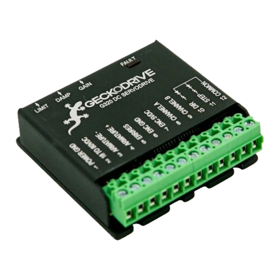
Summary of Contents for Gecko G3 0 Series
- Page 1 ecko G3x0 rror eset ontroller Relays included version Rev 2.
-
Page 2: Design Theory
The newest version of the Gecko 3x0 devices ease the use of this pin by allowing a person to wire all the pins in a system together, but this is still, in my opinion, an incomplete and inflexible solution. - Page 3 • In the event of a fault, indicate which axis caused the fault. If something bad happens to an axis, I want to know which axis. The Gecko gives this information, via an LED turned on inside the case. I want to see it outside the case.
- Page 4 Connecting the GERC_RLY J1 – Power Perhaps the most important connector on the PCB, J1 pin2 is used to connect the DC common of the GERC_RLY (more commonly - if less correctly - known as “ground”) to the DC common (ground) of the motor power supply.
- Page 5 Figure 1 Note: These inputs are a direct, unprotected connection to the microcontroller. Do not connect these inputs to anything except the Error/Reset pin of a Gecko G3x0. J4 - EStop Switch The EStop switch input is a designed to be connected to an external “Big Red Switch”, located in such a position that it is easy for the operator to activate it should the need arise.
- Page 6 Should the switch fail, the GERC_RLY will not allow the motors to turn. Should the wires leading to the switch be cut (by hot swarf, for example), the GERC_RLY will not allow the motors to turn. The GERC_RLY is shipped with a wire jumpering the EStop input, for testing purposes only. As a minimum, an external switch really should be connected.
- Page 7 DC power from the motor’s power supply comes in to pin 1 of the connector, and then to the Normally Open relay contact. The Common relay contact is attached to the connector’s pin 2, and then to the Gecko’s pin2. The Normally Closed relay contact is connected to a power resistor, used for dynamic braking.
- Page 8 “up”, closes the appropriate relay contacts, which then powers the appropriate Gecko(s). Should a Gecko fault or an EStop condition be detected, all relays are opened. Power is now removed from the Gecko(s), and a power resistor connected across the motor terminals. (This connection is actually through the Gecko, not directly to the motor, but the nature of the Gecko output stage is such that this is the correct way to do this.)
- Page 9 1. Power turned on. 2. Toggling the AllStop/Reset switch. Axis fault Should a Gecko detect a fault condition on an axis during normal operation (things working fine), the LED for that axis will blink quickly. A single blinking LED indicates a faulted axis.
- Page 10 Assuming all switches are up … all axes enabled … All GERC_RLY LEDS blink in unison Within 5 seconds, the Gecko LEDs go out. Just after 5 seconds, the GERC_RLY LEDs stop blinking and remain on constantly. GERC_RLY Rev 2 Wiring and Usage manual...
- Page 12 Connector for external ESTOP switch Closed for normal operation EStop Input Relays VEStop ES_In Inputs from G320s C3 - C6 X_In RESET Y_In Z_In A_In DS1233 RA0 6 R6 - R9 RTCC RA1 7 RA2 8 MCLR VEStop 100r x 8 RA3 9 Xstop RELAYS.SCH...
- Page 13 Front Panel PCB +LED SW SPDT +LED SW SPDT +LED XLED YLED +LED SW SPDT ZLED ALED SW SPDT Connector on main PCB +LED SW SPDT Note: SPST throw switches can also be used are ELECTRONICS Title Front panel for G320 error/reset Rev 2 Size Document Number GERC_RLY Date:...
- Page 14 VRelay ES_In VRelay To Motor To Power A_In 50sq100 P&B T90 VRelay To Motor To Power Z_In 50sq100 P&B T90 VRelay To Motor To Power Y_In 50sq100 P&B T90 VRelay To Motor To Power X_In 50sq100 P&B T90 are ELECTRONICS Title GERC Including Relays - Relays Size Document Number...
- Page 15 VEStop Heatsink VCC +5 LM7805 1n5820 220u 220u 220u 110V In 1n5820 MICROTRAN are ELECTRONICS Title GERC with relays - power supply Size Document Number GERC_RLY Date: January 28, 2007 Sheet 4 of...


Need help?
Do you have a question about the G3 0 Series and is the answer not in the manual?
Questions and answers