
Subscribe to Our Youtube Channel
Related Manuals for McIntosh MP1100


Summary of Contents for McIntosh MP1100
- Page 1 McIntosh Laboratory, Inc. 2 Chambers Street Binghamton, New York 13903-2699 Phone: 607-723-3512 www.mcintoshlabs.com MP1100 Phono Preamplifier Owner’s Manual...
-
Page 2: Table Of Contents
Thank You Customer Service Your decision to own this McIntosh MP1100 Phono If it is determined that your McIntosh product is in Remote Control: Preamplifier ranks you at the very top among discrim- need of repair, you can return it to your Dealer. You HR090 Remote Control Push-buttons ...... -
Page 3: General Information
Below is the Pin configuration for the XLR Balanced to the MP1100 Phono Preamplifier. Output Connector on the MP1100. Refer to the dia- 2. The Main AC Power going to the MP1100 and any gram for connections: other McIntosh Component(s) should not be applied... -
Page 4: Introduction
Loading is selectable from values of 50 picofarads to • Selectable Equalizer 400 picofarads. In addition to normal RIAA Equalization Standard, the MP1100 provides the ability to select four alterna- Performance Features • Balanced and Unbalanced Outputs tive Equalization Settings of LP, AES, NAB or 78. - Page 5 Lower Chassis are Stainless Steel with a Mirror Finish. The Upper Chassis and Top Cover is hairline brushed black Titanium Stainless Steel Finish. This will ensure the pristine beauty of the MP1100 will be retained for many years to come.
-
Page 6: Dimensions
Dimensions Dimensions The following dimensions can assist in determining the best location for your MP1100. There is additional information on the next page pertaining to installing the MP1100 into cabinets. Front View of the MP1100 " 44.4cm " 6" 13.7cm 15.2cm... -
Page 7: Installation
Installation Installation " 3/16 The MP1100 can be placed upright on a table or 43.66cm shelf, standing on its four feet. It also can be custom installed in a piece of furniture or cabinet of your choice. The four feet may be removed from the bottom... -
Page 8: Connections
Rear Panel Connections Rear Panel Connections The identification of Rear Panel Connections for the MP1100 Phono Preamplifier is located on a separate folded sheet contained in the Owner’s Manual Packet. Refer to separate sheet “Mc1B” for the Rear Panel Connections. -
Page 9: Connecting Components
Your system 7. Connect an additional Turntable in a similar man- 14. Connect the MP1100 to a live AC Outlet using the may vary from this, however the actual components ner, as outlined in steps 5 and 6. -
Page 10: Front Panel Displays, Controls, Push-Buttons
STANDBY/ON Push-button the audio from the Loud- with indicator, switches the speakers and Headphones MP1100 ON or OFF (Standby) and resets the microprocessors INFORMATION DISPLAY indicates the Sources, Resis- tive value in Ohms and Capacitance value in Picofarads, other Audio Settings, Operational Functions and Setup... -
Page 11: Front Panel Information Displays Modes
Front Panel Information Displays Modes Indicates the type of Phono Cartridge or Indicates the current Playback the Custom Cartridge Profile Setting Equalizer Setting Indicates the current Input Source Selection Operational PHONO 1 RIAA Information pF 50 Ohm=47k Display Indicates the current Phono Indicates the current Phono Cartridge Resis- Cartridge Capacitance Setting tance Setting... -
Page 12: Hr090 Remote Control Push-Buttons
ON and OFF LED illuminates during the time a remote command is sent and when programming the remote control Adjusts the Volume Up or Down on a McIntosh Mutes the audio Component that is IR Code Compatible Steps through the available INPUTS... -
Page 13: How To Operate The Setup Mode
3. Rotate the INPUT Control to select the next Setup software that is know as Firmware. The Version of the Mode Menu item, “SETUP: Input On/Off, (Hold Firmware in the MP1100 can be identified at any time Figure 4 MP1100 V1.00... -
Page 14: Rename Input
“L” to “I”. Refer to figure 9. (refer to page 9, step 8). RENAME: LINE 1 RENAME: BAL 1 The MP1100 Default Input Names (PHONO 1, >INTGRT < PHONO 2, PHONO 3, LINE 1, etc.) as indicated on >IINE 1 <... -
Page 15: Profile Store
PHONO 3 MT10** 200 pF 400 Ohms 58dB STEREO 96kHz LINE 1 * Default settings for MM (Moving Magnet) and MC (Moving Coil) Phono Cartridge Types LINE 2 ** Default settings for Phono Cartridges supplied with McIntosh MT5 and MT10 Turntables... -
Page 16: Digital Output
IR Sensor Digital Output The MP1100 Front Panel Sensor, which receives the One of the MP1100 features is to provide Analog Au- The MP1100 Top Cover Window allows viewing of signals from the HR090 Remote Control, can be dio to Digital Audio (DAC) Signal Conversion for the the four Vacuum Tubes. -
Page 17: Power Mode
Setup, con’t Power Mode Factory Reset The MP1100 incorporates an Auto Off Feature, which If it becomes desirable to reset all the adjustable set- automatically places the preamplifier into the Power tings (Setup and Trim Settings) to the factory default Saving Standby Mode. -
Page 18: How To Operate The Mp1100
Front Panel Display Line 1 by an Equal Symbol (=) between the Loading Type lights to indicate the MP1100 is in Standby mode. To switch ON the MP1100, press the STANDBY/ON and Value. To change the current Resistance Load... - Page 19 Control to select “CAPACITANCE, pF 50” as Change the Resistance Load Setting for a selected the MP1100 has the ability to store up to five addition- indicated on the Front Panel Information Display. Phono Cartridge by performing the following Steps: al Custom Cartidge Profile Settings.
- Page 20 How to Operate the MP1100, con’t standard known as “LP” using microgroove tech- CAPACITANCE GAIN nology. In 1956 the Record Industry Association of pF 300 46dB America (RIAA) established a new standard utilizing Figure 73 the “LP” microgroove technology along with a two...
- Page 21 Reduce unwanted High Frequence Noises known most recordings, the default setting of Digital Output Settings, refer to page 27. as Scratches by using the MP1100 Scratch Filter. To High Setting will produce excellent results. Refer- After approximately 6 seconds the Information...
- Page 22 After approximately 6 seconds the Information METER ILLUMINATION Display returns to indicate the Source Selection and 192kHz The MP1100 Front Panel Meter Illumination may be Settings. switched On or Off by performing the following: Figure 90 After approximately 6 seconds the Information 1.
-
Page 23: Mute, Trim And Output Meters
The Meters are calibrated in dB (decibels) and respond Display returns to indicate the Source Selection and to all the peaks contained in the musical information. Settings. A meter reading of 0dB indicates the MP1100 is deliv- ering its rated output. -
Page 24: Usb Input And Installing Software
PC Windows Driver. Follow the instruc- rear panel USB connector. tions below to install the McIntosh MP1100 Driver: Notes: 1. The MP1100 USB Output is for direct connec- tion to a computer USB using a single input only. Purpose: To Install the McIntosh USB Audio... - Page 25 Audio” from available playback devices The most versatile way of making a digital recording listed when using this McIntosh Product is by using the USB Connection between the MP1100 for USB Audio. and a computer using a Digital Recorder Application.
-
Page 26: Reset Of Microprocessors
How to Operate the MP1100, con’t How to Operate the MP1100, con’t Reset of Microprocessors In the unlikely event the controls of the MP1100 stop functioning, the microprocessors can be reset by per- forming the following: 1. Press and hold in the STANDBY/ON Push-button until all the Front Panel LEDs start flashing, then release the STANDBY/ON Push-button. -
Page 27: Graphic Curves
MP1100 Graphic Curves MP1100 Graphic Curves LP Equalizer Frequency Response Phonograph Record Playback Equalizer +25dB In order to increase the music playback time and +20dB reduce noise of a Record Disc, several different Equal- +15dB +10dB izer Curves have been used over the last 100 years. -
Page 28: Rumble And Scratch Filter Curves
MP1100 Graphic Curves, con’t MP1100 Rumble Filter Frequency Response 78 Equalizer Frequency Response +5dB +25dB +0dB +20dB -5dB +15dB -10dB +10dB -15dB +5dB +0dB -20dB -5dB -25dB -10dB -30dB -15dB -35dB -20dB -25dB -40dB 20Hz 50Hz 100Hz 200Hz 500Hz 1kHz... -
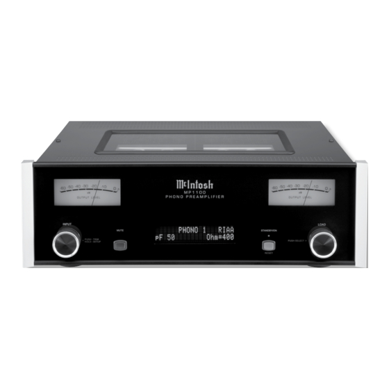
Page 29: Photo
Photo... -
Page 30: Specifications
Line In - 0dB 240 Volts, 50/60Hz at 50 watts 2V Unbalanced Standby Power, less than 0.5 watts Output Impedance Note: Refer to the rear panel of the MP1100 for the cor- rect voltage. Maximum Voltage Output 100 ohms Unbalanced 20V RMS Balanced... -
Page 31: Packing Instruction
400159 #10-32 x 3/4” screw needed, please call or write Customer Service Depart- 404080 #10-7/16” Flat washer ment of McIntosh Laboratory. Refer to page 2. Please see the Part List for the correct part numbers. - Page 32 McIntosh Laboratory, Inc. 2 Chambers Street Binghamton, NY 13903 www.mcintoshlabs.com The continuous improvement of its products is the policy of McIntosh Laboratory Incorporated who reserve the right to improve design without notice. Printed in the U.S.A. McIntosh Part No. 04170800...
Need help?
Do you have a question about the MP1100 and is the answer not in the manual?
Questions and answers