
Related Manuals for BIRD 4043E


Summary of Contents for BIRD 4043E
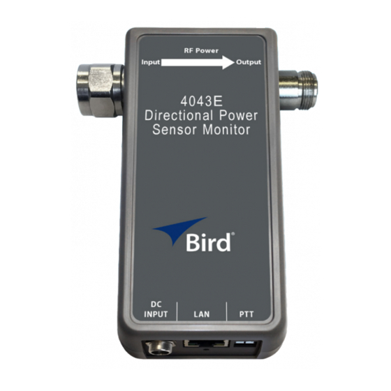
- Page 1 Directional Power Sensor Model 4043E Operation Manual ©Copyright 2021 by Bird Technologies, Inc. Instruction Book Part Number 920-4043E Rev. A...
-
Page 2: Safety Precautions
Safety Precautions The following are general safety precautions that are not necessarily related to any specific part or procedure, and do not necessarily appear elsewhere in this publication. These precautions must be thoroughly understood and apply to all phases of operation and maintenance. WARNING Keep Away From Live Circuits Operating Personnel must at all times observe general safety precautions. -
Page 3: Safety Symbols
Safety Precautions Safety Symbols WARNING Warning notes call attention to a procedure, which if not correctly performed, could result in personal injury. CAUTION Caution notes call attention to a procedure, which if not correctly performed, could result in damage to the instrument. Note: Calls attention to supplemental information. -
Page 4: Safety Statements
Directional Power Sensor 4043E Safety Statements USAGE ANY USE OF THIS INSTRUMENT IN A MANNER NOT SPECIFIED BY THE MANUFACTURER MAY IMPAIR THE INSTRUMENT’S SAFETY PROTECTION. EL USO DE ESTE INSTRUMENTO DE MANERA NO ESPECIFICADA POR EL FABRICANTE, PUEDE ANULAR LA PROTECCIÓN DE SEGURIDAD DEL INSTRUMENTO. - Page 5 Safety Precautions SERVICE SERVICING INSTRUCTIONS ARE FOR USE BY SERVICE - TRAINED PERSONNEL ONLY. TO AVOID DANGEROUS ELECTRIC SHOCK, DO NOT PERFORM ANY SERVICING UNLESS QUALIFIED TO DO SO. SERVICIO LAS INSTRUCCIONES DE SERVICIO SON PARA USO EXCLUSIVO DEL PERSONAL DE SERVICIO CAPACITADO. PARA EVITAR EL PELIGRO DE DESCARGAS ELÉCTRICAS, NO REALICE NINGÚN SERVICIO A MENOS QUE ESTÉ...
-
Page 6: About This Manual
Introduction — Describes the features of the 4043E Directional Power Sensor. Installation — Describes how to set up and prepare the 4043E Power Sensor for use. Maintenance — This section provides the specifications for the 4043E Power Sensor as well as a model identification table. -
Page 7: Table Of Contents
Table of Contents Safety Precautions ......... i Safety Symbols . -
Page 8: Chapter 1 Introduction
The 4043E Power Sensor uses Ethernet communications for sensor control and measurement data. "Sensor Operation" on page 8 The 4043E Sensor is designed to transfer data over an Ethernet connection. The power sensor requires an external power supply. Each sensor is equipped with RF input and output connectors, one RJ-45 connector for Ethernet communications, a PTT connector, and a status indicator. - Page 9 Reset Button default of 192.168.3.200. When long pressed (more than 5 seconds), all of the 4043E settings are reset to the factory defaults. Solid green: Power applied during boot-up. Status LED Blue flashing: Normal operation. Red: Reset button pressed and released.
-
Page 10: Ethernet Measurement Interface
Directional Power Sensor 4043E Ethernet Measurement Interface The 4043E sensor displays measurement information on a Web UI. Using a web browser, enter the IP address for the 4043E to display the web page. Table view displays the current Forward, Reflected, and VSWR measurements. -
Page 11: Chapter 2 Power Sensor Installation
PC and a single 4043E. This connection can be used to view the sensor’s measurement data, however, if the sensor will be used with a LAN connection, this type of connection must be used to change the IP address of the 4043E. See "Direct PC Ethernet Connection" on page 5 LAN Connection —... -
Page 12: Direct Pc Ethernet Connection
PC or SNMP management software. The 4043E sensor’s IP address should be set to a unique static IP address or set to DHCP so the IP address can be assigned when the sensor is connected to the network. -
Page 13: Rf Connections
Figure 5 IP Address Configuration 3. Connect a standard Ethernet cable to the LAN connector on the 4043E and an open connector on a network switch or router. 4. Launch your web browser on a PC connected to the same network as the 4043E. -
Page 14: Ptt Connections
Directional Power Sensor 4043E PTT Connections PTT may be set to normally open or normally closed logic. The PTT terminals must be in the correct logic state for PTT to operate correctly. Note: PTT input is a passive connection and requires a 5V TTL signal to operate. -
Page 15: Chapter 3 Sensor Operation
Chapter 3 Sensor Operation User Interface The User Interface provides a way to view the RF measurements made by the 4043E. Table view displays the current Forward, Reflected, and VSWR measurements. See Figure 7 Figure 7 Web UI, Table View Measurement Display The User Interface also provides the following capabilities: ... -
Page 16: Rf Measurement Alarms
Directional Power Sensor 4043E RF Measurement Alarms The 4043E power sensor can be set to display an alarm, and send SNMP messages, for exceeding forward power and VSWR limits set by the user. Alarms are controlled on the settings page, a threshold can be set for minimum and maximum forward RF power in watts and minimum and maximum VSWR. -
Page 17: Ptt Settings
Figure 10 PTT Options Zero Sensor Zero Sensor is used if the 4043E sensor’s readings are not zero when the RF transmitter connected to the sensor is off. The Zero Sensor option merely applies a negative offset to the power reading based on the value the sensor displays when RF is off. -
Page 18: Implement Snmp
4043E. The SNMP GET operation is used to query the scalar variables in a MIB. Each variable is identified by its OID. The 4043E will respond with a return value or with an error. - Page 19 Sensor Operation SNMP Traps Traps are messages sent to the SNMP manager by the 4043E when events occur. To enable SNMP Trap functionality, connect to the 4043E User Interface, enable Traps, and enter the SNMP Manager’s IP address. See Figure 12 A trap message will be sent to designated host computers whenever the sensor detects an alarm condition.
- Page 20 Directional Power Sensor 4043E Table 1 SNMP Trap Message Definitions Table 1 Name Message Alarm/Clear Description "Alarm" when sensor state changes to an alarm Site Name, Alarm that occurs state. "Clear" when Sensor Name, when the VSWR is MinVSWRAlarmTrap sensor state changes...
-
Page 21: Set Ip Address
Each device on a network must have a unique IP address. The 4043E sensor may be set to use a Static IP address or set to DHCP and assigned an IP address. If Static is chosen, a unique IP address and netmask must be entered into the fields on the Sensor Network Configuration Screen. -
Page 22: Update Sensor Firmware
Directional Power Sensor 4043E Update sensor firmware The 4043E sensors functionality is enabled by firmware installed on the sensor. This firmware can be updated by accessing the firmware update utility on the 4043E sensor’s User Interface webpage. Firmware updates are designed to load completely remote with out user interaction at the installation site. -
Page 23: Chapter 4 Maintenance
Press and hold the reset button for a minimum of 5 seconds, then release the button, the Status LED will briefly change to red. All of the 4043E settings will be reset to the factory defaults. The reset will take approximately 30 seconds to complete. -
Page 24: Customer Service
If the unit needs to be returned for any reason, request an Return Material Authorization (RMA) through the Bird Technologies website. All instruments returned must be shipped prepaid and to the attention of the RMA number. -
Page 25: Chapter 5 Specifications
Chapter 5 Specifications Specification Value True Average forward and reflected power Measurement Type and VSWR 118 to 940 MHz Frequency Range (model dependent) "Model Identification" on page 19 for frequency range of each model. Forward Power Measurement Range 25W to 500W Reflected Power Measurement Range 2.5W to 50W RF Connectors... -
Page 26: Model Identification
Directional Power Sensor 4043E Model Identification... -
Page 27: Limited Warranty
Limited Warranty All products manufactured by Seller are warranted to be free from defects in material and workmanship for a period of one (1) year, unless otherwise specified, from date of shipment and to conform to applicable specifications, drawings, blueprints and/or samples. Seller’s sole obligation under these warranties shall be to issue credit, repair or replace any item or part thereof which is proved to be other than as warranted;...
Need help?
Do you have a question about the 4043E and is the answer not in the manual?
Questions and answers