Table of Contents
Advertisement
Quick Links
Advertisement
Table of Contents

Summary of Contents for Bossard 035/E32V
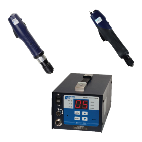
- Page 1 OPERATORS MANUAL FOR ELECTRIC SCREWDRIVERS for self-cutting Threaded Inserts...
-
Page 2: Table Of Contents
ELECTRIC SCREWDRIVERS FOR SELF-CUTTING THREADED INSERTS TABLE OF CONTENT 1. BOSSARD DISCLAIMER 2. INTRODUCTION 3. SCREWDRIVER 3.1 IMPORTANT – INSTALLATION & SAFETY ..........5 3.2 SETTING UP YOUR SCREWDRIVER AND CONTROLLER . -
Page 3: Bossard Disclaimer
Bossard, within a twelve-month period from receipt of goods or proportionally less if the working day is greater than eight hours, Bossard reserves the right to request the equipment be sent direct to the manufacturer of the original equipment. -
Page 4: Introduction
2. INTRODUCTION This manual has been published to offer assistance in the set-up, operation and maintenance of the machine you recently purchased from Bossard. Before you operate the machine please ensure that you have read and fully understood this manual. -
Page 5: Screwdriver
ELECTRIC SCREWDRIVERS FOR SELF-CUTTING THREADED INSERTS 3. Screwdriver 32V and 40VDC 035/E/A CESL8 Brushless Screwdrivers and Controllers - Operation Manual CAUTION – Please read, understand, and follow all operating and safety instructions in this manual before using the tools and controllers. The 035/E/A / CESL8 Series Brushless tools are designed for exclusive use with specific Delta Regis cont- rollers as defined in this manual. -
Page 6: Setting Up Your Screwdriver And Controller
16. Do not attempt to disassemble or repair the screwdriver or controller. Repairs should only be perfor- med by qualified technicians properly trained in the safe operation, troubleshooting, and repair of these devices. Please consult Bossard. 17 Use only the factory specified brand replacement parts and accessories with these tools and controllers. -
Page 7: Before You Turn On The Controller
Ensure that the controller’s power is switch is in the ‘off’ position. Connect the 6-pin tool cable to the screwdriver. The cable has a spring guard at the one end for added protection and durability. Plug this end of the cable into the tool. The connector is designed to be a tight fit – seat the connector firmly into the receptacle and tighten the nut securely by hand. -
Page 8: Operating The Screwdriver
3.4 OPERATING THE SCREWDRIVER All models have a forward/reverse switch. Grip the screwdriver so that the index finger is comfortably over the trig- ger (Start Lever) mechanism and the thumb can be used to change the position of the fwd/rev switch if required. Hold securely to prevent the screwdriver from rotating in the hand during use. -
Page 9: General Screwdriver Layout
3.6 GENERAL SCREWDRIVER LAYOUT 1) Torque Adjusting Nut Turn CW to increase torque setting, CCW to decrease torque output. Higher values on scale indicate a higher torque setting. Please note – numbers (1-8) on the scale are for reference only and are not actual torque values. 2) Start Lever Press to start the screwdriver and hold until the driver shuts off (CW tightening). -
Page 10: Model Numbers And Specifications
3.7 MODEL NUMBERS AND SPECIFICATIONS 3.7.1 32VDC CESL8 SCREWDRIVERS 035/E/A/0.3-32V / 0.29 – 1,86Nm Brushless Electric Screwdriver 32V DC. (2.6 - 16.5 IN/ LBS) 0.29 -1.86 Nm range, 700 / 1.000 rpm 035/E/A1.0 - 32V / 0,98 - 2,94 Nm Brushless Electric Screwdriver 32V DC. -
Page 11: Slow Start / Output Signal Modules
There is no warranty or merchantability or fitness of purpose. In no event will Bossard / Delta Regis Tools, Inc. be liable for business interruptions, loss of profits, harm, injury, damage, personal injury, cost of delay,... -
Page 12: Screwdriver Controller
4.0 SCREWDRIVER CONTROLLER 035/E40V & 035/E32V / BECT940 / 832N-SSO Screwdriver Controller – Operation Manual CAUTION – Please read, understand, and follow all operating and safety instructions in this manual before using the035/40V & 035/E32V / BECT832N / 940-SSO controller. -
Page 13: Specifications
Please consult Bossard for the location of the nearest service depot. 17. Use only the factory specified Delta Regis brand replacement parts and accessories with these tools and controllers. - Page 14 Count Method (selectable) Count up total / count down from total Count Setting Range (rundown) 1 – 99 Time Windows Settings Minimum acceptable rundown time 0.00 – 9.90 seconds (0.01 sec increments) Maximum acceptable rundown time 0.00 – 9.90 seconds (0.1 sec increments) Aduble Alarm Settings (selectable) "On"...
-
Page 15: General Controller Overview
4.3 GENERAL CONTROLLER OVERVIEW Front Face of Controller Screwdriver Hi/Lo Speed Selector Program Function Key Lock Keypad and Indicators for Programming and Status Monitoring Screwdriver Cable Connector Rear Panel of Controller Main Power ON/OFF Switch AC Input Cable Receptacle Input / Output Connection Terminal Block Dip Switch for Selecting Optional Functions Dip Switch for Selecting Optional Functions 4.4 GETTING STARTED... -
Page 16: Keypad And Programming Basics
Plug the controller into a properly grounded AV outlet. Turn ON the main power switch on the back of the controller. The audible alarm will beep, the RUN indicator LED (green) will light up, and the display panel will show the starting batch count value. One of the three output voltage LED indicators (24/32/40V) will be lit up, indicating the controller’s output voltage to the tool. -
Page 17: Program Options And Editing
4.6 PROGRAM OPTIONS AND EDITING 4.6.1 SEQUENCE NUMBER (SL) There are 5 programmable screw fastening sequences (SL = ‘U1’ to ‘U5’) available. In many cases, only the first sequence (U1) will be needed. If the screwdriver is used to install a batch of fasteners with varying requirements, multiple sequences may be necessary. -
Page 18: Maximum And Minimum Rundown Time Settings (Ht, Lt)
4.6.5 MAXIMUM AND MINIMUM RUNDOWN TIME SETTINGS (HT, LT) The controller determines whether a fastener rundown is deemed GOOD (OK) or NO GOOD (NG) by compa- ring the actual time taken for the rundown cycle to a time window programmed by the user. For example, a cross threaded screw will cause the screwdriver to shut-off too early (before min time) and the stripped screw will cause the driver to run too long (beyond max time) NO GOOD (NG) -
Page 19: Detailed Program Editing
4.6.7 DETAILED PROGRAM EDITING START -EDIT Notes and Guidelines: PROGRAM Press and hold SELECT Programming Mode Locks for about 5 seconds until 'SL' displays. To view or edit the sequences, the KEY Adjust value Release to view pro- LOCK must be unlocked and the software grammed value UP / DOWN lock (toggled by pressing SELECT + UP... - Page 20 continued from previous page ... (LL) Re-Hit Screw Time Programming of the (LL) value is only avai- lable if Slow Start Time (RC) is set to 0.0 Press until (slow start off). The re-hit function can't be 'LL' displays. used in conjunction with slow start. Release to Adjust value view value.
- Page 21 Optional 'dt' and 'tt' Cycle Time Alarms. other misc options Two optional alarms are provided to alert the operator if too much time is being taken to run the screws into the assembly. The 'dt' Standby Time Alarm can be set in 1 second intervals. It is the allowable time to run each screw cycle.
-
Page 22: Screwdriver Speed Adjustments
4.6.8 SCREWDRIVER SPEED ADJUSTMENTS The controller determines whether a fastener rundown is deemed GOOD (OK) or NO GOOD (NG) by compa- ring the actual time taken for the rundown cycle to a time window programmed by the user. For example, a cross threaded screw will cause the screwdriver to shut-off too early (before min time) and the stripped screw will cause the driver to run too long (beyond max time) The controller provides two speed control options for the tool –... -
Page 23: Input / Output Connector
4.6.10 INPUT / OUTPUT CONNECTOR... -
Page 24: Dip Switch Settings
4.6.11 DIP SWITCH SETTINGS... -
Page 26: Display Codes
There is no warranty of merchantability or fitness of purpose. In no event will Bossard / Delta Regis Tools, Inc be liable for business interruptions, loss of profits, harm, injury, damage, personal injury, cost of delay,... - Page 27 www.bossard.com...
Need help?
Do you have a question about the 035/E32V and is the answer not in the manual?
Questions and answers