Table of Contents
Advertisement
Advertisement
Table of Contents

Related Manuals for WiXHC MK IV Series


Summary of Contents for WiXHC MK IV Series
- Page 1 MACH3 Motion Card version Manual (MKX...
-
Page 2: Table Of Contents
1. Mach3 Software installation 2. Drive and configuration file installation 2.1 Drive installation 2.2 Configuration file installation 2.3 Macro code file installation 3. How to connect card and pc 3.1 How to connect USB motion card 3.2 How to connect Ethernet motion card 4. - Page 3 5.2 Spindle On/Off 5.3 Jog move 5.4 Go to Home of machine 5.5 Go to Zero 5.6 Manual input G code 5.7 Load G code 5.8 How to control output ports 5.9 Z Auto Tool Zero 6. Mach3 Software parameters 6.1 Motor tuning 6.2 Ports and Pins 6.2.1 Motor outputs...
-
Page 4: Mach3 Software Installation
Software installation 1.Mach3 Software installation 1.1 You can install the software we provide :Mach3Version 3.043.066,or download from MACH3's website. Open our CD,find Mach3 Soft>>Mach3Version3.043.066 ,click it to installation.( see Figure ) 1.2 When you install it, please cancel “Parallel Port Driver ” option.(see Figure)... - Page 5 Software installation 1.3 After the software installation is completed, you need to copy ‘Mach1Lic.dat’file to C:/Mach3 folder.
-
Page 6: Drive And Configuration File Installation
Software installation Configuration file Driver and 2.1 Driver installation Please copy the driver file after the software installation is complete. Open our Cd,and find the...English manual>>Driver file>> NcUsbPod.dll (Ethernet control card driver is NcEther.dll ).Then copy it to MACH3 software folder...C:/Mach3>> PlugIns folder (see Figure)... -
Page 7: Macro Code File Installation
Software installation NOTE:After you copy the file ,all basic parameters have been set up. Only the motor parameters need to be set. Please do not modify other parameters. 2.3 Macro code file installation When you need to control the output port or other macro code functions, you must copy them to...C:/MACH3>>macros>... -
Page 8: How To Connect Card And Pc
Wiring diagram How to connect card and computer 3.1 How to connect USB port card and computer NOTE: Please use the cable that we provide, and don't extend it. Connect the computer and USB card with the USB cable. There is a work indicator light on the control card. If flashing means the connection is successful.Or check your computer device manager>>Human body input device,check whether there is new equipment added. - Page 9 Connect computer you need manually set the IP address in your pc : 1.WindowsXP Click right mouse button on “My Network Places” icon and select “Properties” position from the menu. You will see window with the icons/icon of network connections. Click right mouse button on “...
-
Page 10: Hardware Wiring
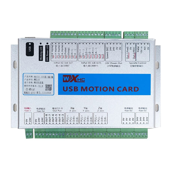
Wiring diagram 4.Hardware wiring Wiring diagram 4.1 Power Supply The control card need DC24V/1A as power ﹣ ﹢ 24V power... -
Page 11: Driver Connection
Wiring diagram 4.2 Driver connection 4.2.1 MKX-IV motion card driver wiring MKX-IV motion card X.Y.Z.A axis outout port: XD- XP- 5V YD- YP- 5V ZD- ZP- 5V AD- AP- Port Function Note X axis Direction output X axis driver DIR- port X axis Pulse output X axis driver PUL- port 5V output... -
Page 12: Mkx-V Motion Card Driver Wiring
Wiring diagram 4.2.2 MKX-V motion card driver wiring MKX-V motion card X axis output port:(Same as other axis) PUL+ PUL- DIR+ DIR- Port Function NOTE X axis driver PUL+ PUL+ X axis Pulse output Positive X axis driver PUL- PUL- X axis Pulse output Negative X axis driver DIR+ DIR+... -
Page 13: Spindle Connetion
Wiring diagram 4.3 Spindle connection 4.3.1 Spindle frequency converter Spindle output port FWD 0V(DCM) REV PWM 10V-in AVI 0V(ACM) Function NOTE Port Spindle for ward signal Converter for ward For ward signal ground 0V(DCM) For ward GND Spindle reverse signal Converter reverse Spindle PWM output Converter PWM... -
Page 14: Driver
Wiring diagram 4.3.2 Spindle driver Spindle connect stepper or ser vo driver, you need a 5V power supply, wiring as shown below Control Board Driver DIR+(5V) DIR- PUL+(5V) PUL- 10V-in ﹢ ﹣ DC5V power... -
Page 15: Home Switch
Wiring diagram 4.4 Home switch Support NPN/PNP switch. Active low. Input current 5 mA, 24V Home switch input port: In0(X-HOME) In1(Y-HOME) In2(Z-HOME) In3(A-HOME) NOTE Port Function X axis home signal X axis home switch In0(X-HOME) Y axis home signal Y axis home switch In1(Y-HOME) Z axis home signal Z axis home switch... - Page 16 Wiring diagram ② The PNP switch requires a relay switch Common types :SN04-P,SN05-P,SN10-P,SC1202-P,SC1204-P PNP switch control board brown 24V +24V blue 0V(GND) In0(X-HOME) black OUT relay ③Mechanical switch, active low control board In0(X-HOME)
-
Page 17: Limit Switch
Wiring diagram 4.5 Limit switch Support NPN/PNP switch. Active low. Input current 5 mA, 24V Limit switch input port: (Take the X.Y axis as an example) In6(X++) In7(X--) In8(Y++) In9(Y--) Port Function NOTE X positive limit signal X axis positive limit In6(X++) X negative limit signal In7(X--) - Page 18 Wiring diagram ② The PNP switch requires a relay switch Common types :SN04-P,SN05-P,SN10-P,SC1202-P,SC1204-P PNP switch control board brown 24V +24V blue 0V(GND) In6(X++) black OUT relay ③Mechanical switch, active low control board In0(X-HOME)
-
Page 19: Tool Setting Gauge
Wiring diagram 4.6 tool setting gauge Probe input port: In4(PROBE) 24V Port Function NOTE In4(PROBE) tool setting gauge signal Probe Z input signal 24V output tool setting gauge 24V 0V Ground tool setting gauge 0V (GND) tool setting gauge control board +24V +24V 0V(GND) -
Page 20: Emergency Stop Button
Wiring diagram 4.7 Emergency stop button Support emergency stop signal input.Active low. Emergency stop signal input port: In5(ESTOP) NOTE Port Function Emergency stop signal Emergency stop signal In5(ESTOP) signal ground control board In5(ESTOP) Stop button... -
Page 21: Relay Connection
Wiring diagram 4.8 Relay connection MKX control board with 8 output port. OUT1 is spindle for ward signal,OUT2 is spindle Reverse signal.OUT3-OUT8 port ,you can connect relays, relays can control cooling pump, etc. Supports maximum 24V, 80 mA relay.Active low. Output port: OUT3 OUT4 OUT5 OUT6 OUT7 OUT8 24V control board... - Page 22 Wiring diagram If you connect Solid state relay, you need series connect a 1K/1W resistance. control board OUT3 OUT4 1K/1W ﹣ OUT5 ﹢ Solid state relay...
-
Page 23: Mach3 Software Operation
Software operation 5.Mach3 software operation 5.1 Open and Loading interface Click on“Mach3mill”icon to open software, If there is an interface to select the plug-in,please chose “NcusbPod-XHC -Mach3-USB-Motion-Card”(see Figure). If you open the software, there is a blank interface,please chose...View>>Load screens,then chose screen file(see Figure) -
Page 24: Spindle On/Off
Software operation 5.2 Spindle ON/Off You can press the "Spindle CW F5”button to open or close spindle.(see Figure),and you can manual input G code:M3( Spindle on),M5(Spindle off) Spindle CW F5: Press the button Spindle on or off. SRO%: S-oV: Spindle speed Spindle current percentage, speed... -
Page 25: Jog Move
Software operation 5.3 Jog move Press the computer keyboard "Tab” key, Cycle Jog Step: Jog Mode: press the button Press the button, chose Step value chose jog mode. '0.1 “Cont”,”Step” 0.01 mm .etc. ,”MPG” Slow Jog Rate: Percentage of Jog move speed. -
Page 26: Go To Home Of Machine
Software operation 5.4 Go to Home of machine Press “REF ALL HOME”button, all axis will going to home of machine and coordinate clearing.You can click the “Machine coord`s”to see machine coordinate. 5.5 Go to Zero Press the “Zero X””Zero Y””Zero Z””Zero 4”buttons, The workpiece coordinates are cleared and set to the Zero of the workpiece.Click the “GOTO ZERO”... -
Page 27: Manual Input G Code
Software operation 5.6 Manual input G code When you need input G code,please click the “MDI(Alt-2)” ,then click the “Input”and input G code. 5.7 Load G code MACH3 software only supports G code files. Please choose "File">>"Load G-code",and choose your processing file. -
Page 28: How To Control Output Ports
Software operation After the program is loaded, click “Cycle Start”and the program starts running;Click “Feed Hold” and program pause; Click “Reset”and software emergency stop. 5.8 How to control output ports If you connect relays to control board output ports,you need some M macro code to control output ports ON or OFF. Open our CD, ...English Manual>>macro folder, and cpoy all M code to...C:/Mach3/macros/Mach3Mill folder. -
Page 29: Z Auto Tool Zero
Software operation 5.9 Z Auto Tool Zero 1.Open our CD... English Manual>>macro folder, and cpoy M930 code to...C:/Mach3/macros/Mach3Mill folder. 2.Open the M930 file in TXT format,then copy all program code. Open MACH3 software, click the "Operator"option,click ”Edit button script”,(Figure 1).Then click “Auto Tool Zero” button,delete the code in the button script, and then paste the copied M930 code program.(Figure 2)... - Page 30 Software operation...
-
Page 31: Mach3 Software Parameters
Basic parameters MACH3 Software parameters 6.1 Motor tuning Open Mach3 software,select "Config">>“Motor tuning” option, In the window, first select an axis you want to configure, next enter parameters and click „SAVE AXIS SETTINGS”. Now you can select and set the next axis. If we forget to click on „ SAVE AXIS SETTINGS”... -
Page 32: Ports And Pins
Basic parameters 6.2 Ports and Pins 6.2.1 Motor outputs Open Mach3 Software,select "Config">>“Ports and Pins” >>“Motor tuning” Enable: Tick to make the axis output Dir Lowactive: Motor direction selection Step Lowactive: Tick to make the axis output 6.2.2 Input signals Open Mach3 software,select "Config">>“Ports and Pins”... -
Page 33: Output Signals
Basic parameters Enable: Tick to enable input ports Pin Number: The control card input port Active Lovw: Low level active, tick to enable 6.2.3 Output signals Open Mach3 software,select"Config">>“Ports and Pins” >>“Output signals ” Enable: Tick to enable output ports Pin Number: The control card output port Active Lovw:... -
Page 34: Spindle Setup
Basic parameters 6.2.4 Spindle setup Open Mach3 software,select"Config">>“Ports and Pins” >>“Spindle setup”... -
Page 35: Software Limit
Basic parameters Disable spindle relays: Cancel the tick Motor control: if your spindle is VFD, tick “PWM”;if your spindle is driver, tick”Step /dir motor ” 6. 3 Software limit Open Mach3 software,select"Config">>"Homing/limits" option. "Soft Max":Software limit maximum machine coordinates "Soft Min":Software limit minimum machine coordinate After setting up, click the "soft limit"... -
Page 36: Driver Plug-In Control
Basic parameters 6.4 Driver plug-in control Open Mach3 software,select "Config">>"Config Plugins" >>“XHC Ncpod Config”clik “Config”button to open. -
Page 37: Z Safety Height
Basic parameters No Homing: not go to machine origin Single Stage: go to machine origin only once Dual Stage: go to machine origin twice Home Switches: tick “LimitEn”enable,and tick X.Y.Z and so on to allow it to have a limit function GSpeedHigh: Tick ,Increase the arc running speed Pulse per Rotate: if your spindle is driver control by Pulse/... -
Page 38: Motor Direction Of Go To Home
Basic parameters 6.6 Motor direction of go to Home Open Mach3 soft,select"Config">>"Homing and Limits" option,when you click “Ref all home”button, the origin of the direction of an axis error,you can change"Home Neg"option, tick or cancel tick to make it correct. -
Page 39: General Config
Basic parameters 6.7 General Config Open Mach3 soft,select"Config">>" General Config "option A-Axis angular : If your A axis is the axis of rotation, and the angle of rotation is 0-360 degrees.please tick it. Rotational: "Rot 360 rollover": If your A axis is the axis of rotation, the angle of rotation is 0-360 degrees.please tick it.
Need help?
Do you have a question about the MK IV Series and is the answer not in the manual?
Questions and answers