Table of Contents
Advertisement
Quick Links
Table of Contents
2018-03-26
Operating manual
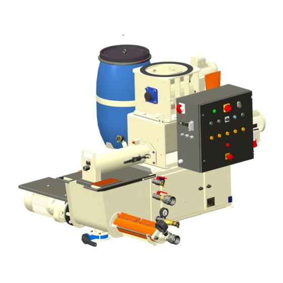
FERRO 100 II
Part 2 Overview – Operation - Spare parts lists
EC Declaration of Conformity
Article number of the operating manual: 00 62 68 00
Article number of the parts list-machine: 00 23 21 39
Article number of the parts list-machine: 00 17 17 05
Article number of the parts list-machine: 00 59 91 16 with water tank complete
Read the operating manual prior to starting any work!
Advertisement
Table of Contents

Related Manuals for PFT FERRO 100 II


Summary of Contents for PFT FERRO 100 II
- Page 1 Table of Contents 2018-03-26 Operating manual FERRO 100 II Part 2 Overview – Operation - Spare parts lists EC Declaration of Conformity Article number of the operating manual: 00 62 68 00 Article number of the parts list-machine: 00 23 21 39...
- Page 2 © Knauf PFT GmbH & Co. KG P.O. Box no. 60 97343 Iphofen Einersheimer Straße 53 97346 Iphofen Germany Phone +49 9323 31-760 Fax +49 9323 31-770 Technical hotline +49 9323 31-1818 info@pft.net www.pft.net 2018-03-26...
-
Page 3: Table Of Contents
FERRO 100 II Part 2 Overview – Operation - Spare parts lists Table of Contents 14 Operating modes of selector switch ..18 Table of Contents 15 Functional description – work flow ..20 EC Declaration of Conformity ..... 6 15.1 Basic equipment ......... - Page 4 FERRO 100 II Part 2 Overview – Operation - Spare parts lists Table of Contents 26 Work on troubleshooting ......34 34.7 Cleaning filters ........49 26.1 Reaction in the event of faults ... 34 34.8 Environmental protection ....50 26.2 Fault displays ........
- Page 5 FERRO 100 II Part 2 Overview – Operation - Spare parts lists Table of Contents 38.22 Control box Art. no. 00208092 38.25 Silo mounting ........81 internal ..........77 39 Index ............82 38.23 Star wheel lock FERRO II complete RAL1015 Article number 00035135 ..
-
Page 6: Ec Declaration Of Conformity
FERRO 100 II Part 2 Overview – Operation - Spare parts lists EC Declaration of Conformity 1 EC Declaration of Conformity Company: Knauf PFT GmbH & Co. KG Einersheimer Straße 53 97346 Iphofen Germany declares under our sole responsibility that the machine:... -
Page 7: Inspection
The inspection results have to be documented and kept at least until the next inspection. Inspection recommendations for the annual expert inspection of the FERRO 100 II (which is to be conducted in accordance with BGR 183) can be found in this section. https://www.pft.net/de/service/downloads/index.php?t=0&p=12&s=0&q=... -
Page 8: General Information
FERRO 100 II Part 2 Overview – Operation - Spare parts lists General information 5 General information 5.1 Information regarding the operating manual This operating manual gives important information on handling the device. A prerequisite for safe working is the observance of all stated safety guidelines and instructions. -
Page 9: Technical Data
FERRO 100 II Part 2 Overview – Operation - Spare parts lists Technical data 6 Technical data 6.1 General information Article number FERRO 100 II 00171705 / 00232139 Detail Value Unit Weight 653 / 675 kg Length approx. 2110 mm Total width approx. -
Page 10: Operating Conditions
FERRO 100 II Part 2 Overview – Operation - Spare parts lists Sound power level 6.3 Operating conditions Environment Detail Value Unit Temperature range 2-45 °C Relative humidity, max. 80 % Duration Detail Value Unit Max. operating time at a stretch 8 hours 6.4 Power values... -
Page 11: Dimension Sheet
FERRO 100 II Part 2 Overview – Operation - Spare parts lists Dimension sheet 10 Dimension sheet 2110 Fig. 3: Dimension sheet 11 Name plate The type plate is located in the control box and includes the following information: Manufacturer... -
Page 12: Overview Of Article Number 00599116
FERRO 100 II Part 2 Overview – Operation - Spare parts lists Overview of article number 00599116 12 Overview of article number 00599116 Fig. 5: Table of the assembly groups 1. Mixing tube / mixer 12. Water installation cabinet 2. Star wheel lock 13. -
Page 13: Overview Of Article Number 00171705
FERRO 100 II Part 2 Overview – Operation - Spare parts lists Overview of article number 00599116 12.1 Overview of article number 00171705 Fig. 6: Table of the assembly groups 1. Material hopper for mixer 5. Dust protection for pump motor 2. -
Page 14: Description Of Assemblies
FERRO 100 II Part 2 Overview – Operation - Spare parts lists Description of assemblies 13 Description of assemblies 13.1 Assembly unit description control box Control box 1. Push button for vibrating unit with manual function. 2. Control lamp machine ready for operation. -
Page 15: Water Supply Heated Art. No
FERRO 100 II Part 2 Overview – Operation - Spare parts lists Description of assemblies 13.2 Water supply heated Art. no. 00186555 Fig. 8: Water supply assembly 1. Pressure reducer 7. Solenoid valve drainage 2. Manometer for hydraulic pressure of the booster 8. - Page 16 FERRO 100 II Part 2 Overview – Operation - Spare parts lists Description of assemblies 13.3 Water supply heated Art. no. 00186555 Fig. 9: Water supply assembly 1. Power connection of the booster pump 5. Water inlet from network or water tank 2.
-
Page 17: Water Supply Heated Art. No
FERRO 100 II Part 2 Overview – Operation - Spare parts lists Description of assemblies 13.4 Water supply heated Art. no. 00232147 Fig. 10: Water supply assembly 1. Strainer chamber for pressure reducer 8. Solenoid valve drainage 2. Pressure reducer 9. -
Page 18: Operating Modes Of Selector Switch
FERRO 100 II Part 2 Overview – Operation - Spare parts lists Operating modes of selector switch 14 Operating modes of selector switch Main switch “ON”, control voltage “ON”, Selector switch position “0”,: Machine is ready for operation, green control lamp lights up. - Page 19 FERRO 100 II Part 2 Overview – Operation - Spare parts lists Operating modes of selector switch Main switch “ON”, control voltage “ON”, Selector switch mixer “Manual”: Mixer is in operation. Mixer is operated separately for filling the pump container.
-
Page 20: Functional Description - Work Flow
Adhere to the usage directives of the material manufacturer. The machine combination PFT FERRO 100 II is in use, ready for connection under a silo / container. The material reaches in the collection tank of the conveying pump by a horizontal mixer equipped with its own drive after addition of water in mixing tube and is forwarded from there at up to 120 l/min to processing plant. -
Page 21: Transport, Packing And Storage
FERRO 100 II Part 2 Overview – Operation - Spare parts lists Transport, packing and storage 16 Transport, packing and storage 16.1 Safety instruction for transport Improper transport ATTENTION! Damage from improper transport! Improper transport may cause substantial property damage. -
Page 22: Transport Inspection
FERRO 100 II Part 2 Overview – Operation - Spare parts lists Transport, packing and storage 16.2 Transport inspection On receipt check the delivery immediately for completeness and transport damage. In case of externally visible transport damage, proceed as follows: Do not accept the delivery or under reserve only. -
Page 23: Transport By Car Or Truck
FERRO 100 II Part 2 Overview – Operation - Spare parts lists Transport, packing and storage 16.4 Transport by car or truck DANGER! Danger of injury by unsecured loads! In case of road transport, all persons involved in the loading process are responsible for the proper securing of the load. -
Page 24: Transport Of Already Running Machine
FERRO 100 II Part 2 Overview – Operation - Spare parts lists Transport, packing and storage 16.6 Transport of already running machine DANGER! Danger of injury from discharged mortar! Injuries to face and eyes can occur. Therefore: Before opening the couplings ensure that there is ... -
Page 25: Packaging
FERRO 100 II Part 2 Overview – Operation - Spare parts lists Packaging 17 Packaging For packaging The individual packages have to be packed in accordance with the transport conditions to be expected. Only environmentally-friendly materials were used for the packaging. -
Page 26: Set Up Silo With Ferro
FERRO 100 II Part 2 Overview – Operation - Spare parts lists Set up silo with Ferro Basic information WARNING! Danger of injury due to incorrect operation! Improper operation may lead to serious damage to persons or property. Therefore: Carry out all operating steps according to the instructions in this user manual. -
Page 27: Preparation
FERRO 100 II Part 2 Overview – Operation - Spare parts lists Preparation 21 Preparation 21.1 Connection of power supply Prior to operating the machine carry out the following steps for preparing the machine: DANGER! Rotating pump shaft! Risk of injury while reaching into the pump material container. -
Page 28: Connecting The Water Supply
FERRO 100 II Part 2 Overview – Operation - Spare parts lists Preparation All the connections should be made or checked before commissioning: Connect the power supply for pump motor (4). Connection dry sensor (5) Connection thermistor (6) Connection wet sensor (7) Fig. - Page 29 FERRO 100 II Part 2 Overview – Operation - Spare parts lists Preparation Put the water hose (2) from the mixing tube in the pump container. Fig. 31: Water hose Set the main reversing switch (3) to ‘I’. If the yellow control lamp “Change direction of rotation” lights up, the direction of rotation at the main switch must be changed.
-
Page 30: Mortar Manometer
FERRO 100 II Part 2 Overview – Operation - Spare parts lists Mortar manometer NOTE! “ON” Before switching over from step switch to other operating modes, the control voltage must be switched off through the push button operation “ON” “OFF”... -
Page 31: Drain Water From Pump Container
FERRO 100 II Part 2 Overview – Operation - Spare parts lists Mortar manometer DANGER! Never loosen the hose couplings as long as there is pressure on the material hoses (check mortar manometer)! The mix could burst out under pressure and result in serious injuries, especially injuries to the eyes. -
Page 32: Putting Ferro Ii Into Service
FERRO 100 II Part 2 Overview – Operation - Spare parts lists Putting FERRO II into service 23 Putting FERRO II into service 23.1 Risk of injury from discharged mortar DANGER! Danger of injury from discharged mortar! Discharged mortar may lead to injuries to eyes and face. -
Page 33: Remote Control
FERRO 100 II Part 2 Overview – Operation - Spare parts lists EMERGENCY STOP situation, end of work or interruption of work 23.3 Remote control Disconnect the dummy connector (1) from the control box and insert the cable from the cable drum using the remote control. -
Page 34: Shutdown In Case Of Emergency
FERRO 100 II Part 2 Overview – Operation - Spare parts lists Shutdown in case of emergency 25 Shutdown in case of emergency Shutdown in case of emergency In dangerous situations machine movements have to be stopped as quickly as possible, and the power supply has to be disconnected. -
Page 35: Fault Displays
FERRO 100 II Part 2 Overview – Operation - Spare parts lists Work on troubleshooting 26.2 Fault displays The following installation indicates faults: Fault displays Pos. Light signal Description Lights up when the motor protection switch has been Control lamp red triggered. -
Page 36: Table Of Faults
FERRO 100 II Part 2 Overview – Operation - Spare parts lists Work on troubleshooting 26.5 Table of faults Fault Possible cause Troubleshooting Rectification by Water No water Pressure switch or solenoid valve Service engineer defective Machine does not start:... - Page 37 FERRO 100 II Part 2 Overview – Operation - Spare parts lists Work on troubleshooting Fault Possible cause Troubleshooting Rectification by Control lamp Overheating of pump motor Shorten mortar hose or increase the Operator “thermistor” cross section; let the pump motor...
- Page 38 FERRO 100 II Part 2 Overview – Operation - Spare parts lists Work on troubleshooting Fault Possible cause Troubleshooting Rectification by Water is not Solenoid valve (hole in membrane Clean solenoid valve Service engineer flowing. blocked) Flow meter Solenoid coil defective...
-
Page 39: Transport Is At A Standstill / Blockage
FERRO 100 II Part 2 Overview – Operation - Spare parts lists Work on troubleshooting 26.6 Transport is at a standstill / Blockage Clogging might form in the feed hoses for several reasons. This means that the material to be conveyed remains stuck in the feed hoses and cannot be pumped to the hose ends. -
Page 40: Change Direction Of Rotation Of The Pump Motor In Case Of Blocked Hoses
FERRO 100 II Part 2 Overview – Operation - Spare parts lists Work on troubleshooting 26.10 Change direction of rotation of the pump motor in case of blocked hoses DANGER! Danger from discharged material! Never loosen the hose couplings as long as the pressure... -
Page 41: Detach Coupling Connections
FERRO 100 II Part 2 Overview – Operation - Spare parts lists Rest 26.11 Detach coupling connections If the blockage cannot be released: Cover coupling connections with tear-proof film. Loosen cam leaver and hose connections. NOTE! Clean material hoses immediately. -
Page 42: Remove The Material Hoses
FERRO 100 II Part 2 Overview – Operation - Spare parts lists Cleaning 28.2 Remove the material hoses Check the mortar pressure gauge if the mortar pressure has lowered to "0". If necessary, change the direction of rotation of the pump motor and let the pump run backwards for a short time. -
Page 43: Cleaning The Mixer
FERRO 100 II Part 2 Overview – Operation - Spare parts lists Cleaning the mixer 29 Cleaning the mixer 29.1 Safety shutdown at the mixing tube Remove the water hose (1) from the mixing tube. Release quick fasteners (2) and remove mixing tube. - Page 44 FERRO 100 II Part 2 Overview – Operation - Spare parts lists Cleaning the machine and pump container Use water jet to free the machine and pump material container from adhering residual floating screed. Fig. 68: Cleaning the pump container Open the butterfly valve and drain off remaining water.
-
Page 45: Action In Case Of Power Failure
FERRO 100 II Part 2 Overview – Operation - Spare parts lists Action in case of power failure 31 Action in case of power failure NOTE! The FERRO II is equipped with a restart interlock. In case of a power cut, the system must be restarted by pressing the push button control voltage ON/OFF. -
Page 46: Maintenance
FERRO 100 II Part 2 Overview – Operation - Spare parts lists Maintenance NOTE! In case of a currentless machine, the solenoid valves of the water supply automatically open and the water can run off, so that there is no more water in the water supply when there is a risk of frost. -
Page 47: Adjust Pump
FERRO 100 II Part 2 Overview – Operation - Spare parts lists Maintenance Secure against restarting DANGER! Danger to life from unauthorised restarting! When working with the tool, there is the risk that energy supply switched without authorisation. This poses a danger to life for the persons in danger area. -
Page 48: Tightening Torque Of Tie Rod Screws
FERRO 100 II Part 2 Overview – Operation - Spare parts lists Maintenance 34.3 Tightening torque of tie rod screws 34.3.1 Do not load the pump unit NOTE! Tighten the tie rod screws of the pump unit with a torque of 98 Newton metres. -
Page 49: Lubrication During Maintenance
FERRO 100 II Part 2 Overview – Operation - Spare parts lists Maintenance 34.6 Lubrication during maintenance Lubrication: Mixer motor and grease retainer unit Lubrication with standard lubricating grease Fig. 81: Lubrication Lubrication: Star wheel lock Fig. 82: Lubrication Weekly check at the inspection glass of the seal unit. -
Page 50: Environmental Protection
FERRO 100 II Part 2 Overview – Operation - Spare parts lists Maintenance Check the water inlet filter in water inlet daily. Filter insert ES 30-1" A: Article number 20152011 Fig. 85: Water inlet filter Electrical system DANGER! Danger to life from electric current! There is danger to life if you come in contact with live parts. -
Page 51: Refilling The Silo
FERRO 100 II Part 2 Overview – Operation - Spare parts lists Refilling the silo 35 Refilling the silo NOTE! The silo can be refilled during operation. 36 Disassembly After the useful service life has expired, the device has to be dismantled and disposed of in an environmental-friendly manner. -
Page 52: Disassembly
FERRO 100 II Part 2 Overview – Operation - Spare parts lists Disposal 36.2 Disassembly Clean the device for phasing out and disassemble under observance of applicable health and safety rules as well as environmental regulations. Prior to starting the disassembly: Switch off device and secure against restarting. - Page 53 FERRO 100 II Part 2 Overview – Operation - Spare parts lists Spare parts drawing, spare parts list 2018-03-26...
-
Page 54: Spare Parts Drawing, Spare Parts List
FERRO 100 II Part 2 Overview – Operation - Spare parts lists Spare parts drawing, spare parts list 38 Spare parts drawing, spare parts list 38.1 Mixer motor / dosing shaft Pos. Quantity Art. no. Name 00193318 Dosing shaft FERRO 100 II RAL1015 manufactured on or before 07.2016 00551148 Dosing shaft FERRO 100 II half-shell RAL1015 manufactured from 08.2016 onwards... -
Page 55: Star Wheel Lock Ferro Ii Complete
FERRO 100 II Part 2 Overview – Operation - Spare parts lists Spare parts drawing, spare parts list 38.2 Star wheel lock FERRO II complete Pos. Quantity Art. no. Name 00035135 Star wheel lock FERRO II complete RAL1015 00008640 Rain cover, filters and hose clamps for CMP and delivery hood 00270211 Geared motor flat gear 0.75 / 400V FERRO RAL1015... -
Page 56: Mixing Tube Ferro Ii
FERRO 100 II Part 2 Overview – Operation - Spare parts lists Spare parts drawing, spare parts list 38.4 Mixing tube FERRO II Pos. Quantity Art. no. Name Quick release fastener with locking device M14 20100801 Mixing shaft FERRO 100 II long half-shell RAL1015 00551154 Magnetic/ safety sensor 2Ö/1S... -
Page 57: Mixing Tube Ferro Ii "Alt
FERRO 100 II Part 2 Overview – Operation - Spare parts lists Spare parts drawing, spare parts list 38.5 Mixing tube FERRO II “ALT” Pos. Quantity Art. no. Name Mixing tube FERRO 100 II RAL1015 complete 00193708 Mixing tube FERRO 100 II RAL1015... -
Page 58: Mixing Tube Ferro Ii "New
Mixing tube FERRO 100 II round RAL1015 00222137 Mixing shaft FERRO 100 II long RAL1015 manufactured on or before 07.2016 00222145 00551154 Mixing shaft FERRO 100 II long half-shell RAL1015 manufactured on or before 08.2016 00080861 Tube nut G 1" 00035571 Lubricating nipple M 8 20203620 Angle 1"... -
Page 59: Pump Container
FERRO 100 II Part 2 Overview – Operation - Spare parts lists Spare parts drawing, spare parts list 38.7 Pump container Pos. Quantity Art. no. Name 00216381 Filllevel sensor KPS1 00023886 Hub D = 35 for FERRO II 00035121 Pump shaft FERRO II RAL1015... -
Page 60: Oil Sealing Unit Ferro Ii
FERRO 100 II Part 2 Overview – Operation - Spare parts lists Spare parts drawing, spare parts list 38.8 Oil sealing unit FERRO II Pos. Quantity Art. no. Name 20205880 Locking screw 1/2”, galvanised 20144021 Slide ring gasket (set) oil sealing unit ZP 3... -
Page 61: Pump Unit Ferro Ii
FERRO 100 II Part 2 Overview – Operation - Spare parts lists Spare parts drawing, spare parts list 38.9 Pump unit FERRO II Pos. Quantity Art. no. Name Pressure flange with manometer FERRO II RAL1015 complete 00194581 Manometer with plastic inlet housing 0-100 bar 1" VA 00099089 Hex. -
Page 62: Water Supply Ferro 100 Ii 00186555
FERRO 100 II Part 2 Overview – Operation - Spare parts lists Spare parts drawing, spare parts list 38.10 Water supply FERRO 100 II 00186555 2018-03-26... -
Page 63: Ferro 100 Ii 00186555
FERRO 100 II Part 2 Overview – Operation - Spare parts lists Spare parts drawing, spare parts list 38.11 Spare parts (ET) list Water supply FERRO 100 II 00186555 Pos. Quantity Art. no. Name 20 20 16 90 High-pressure suction coupling 1" sleeve with gasket 20 20 29 11 Hose clip 34-37 (PACKING UNIT = 10 PCS) 00 00 87 04 Water/air hose 1"... -
Page 64: Water Supply Ferro 100 Ii 00186555
FERRO 100 II Part 2 Overview – Operation - Spare parts lists Spare parts drawing, spare parts list 38.12 Water supply FERRO 100 II 00186555 2018-03-26... -
Page 65: Ferro 100 Ii 00186555
FERRO 100 II Part 2 Overview – Operation - Spare parts lists Spare parts drawing, spare parts list 38.13 Spare parts (ET) list Water supply FERRO 100 II 00186555 Pos. Quantity Art. no. Name 00 09 86 55 Motor connection cable 0.85m water pump 400V 00 49 18 37 Booster pump AV1000/1 230/400V 50Hz 20 20 36 50 Angle 1/4"... -
Page 66: Water Supply Ferro 100 Ii 00232147
FERRO 100 II Part 2 Overview – Operation - Spare parts lists Spare parts drawing, spare parts list 38.14 Water supply FERRO 100 II 00232147 2018-03-26... -
Page 67: Ferro 100 Ii 00232147
FERRO 100 II Part 2 Overview – Operation - Spare parts lists Spare parts drawing, spare parts list 38.15 Spare parts (ET) list Water supply FERRO 100 II 00232147 Pos. Quantity Art. no. Name 00 02 20 73 CEE socket outlet 4 x 16A 6h, red 00 09 86 55 Motor connection cable 400 V - 0.85 m... -
Page 68: Water Supply Ferro 100 Ii 00232147
FERRO 100 II Part 2 Overview – Operation - Spare parts lists Spare parts drawing, spare parts list 38.16 Water supply FERRO 100 II 00232147 2018-03-26... -
Page 69: Ferro 100 Ii 00232147
FERRO 100 II Part 2 Overview – Operation - Spare parts lists Spare parts drawing, spare parts list 38.17 Spare parts (ET) list Water supply FERRO 100 II 00232147 Pos. Quantity Art. no. Name 20 20 16 90 High-pressure suction coupling 1" sleeve with gasket 20 20 29 11 Hose clip 34-37 (PACKING UNIT = 10 PCS) 00 00 87 04 Water/air hose 1"... -
Page 70: Control Box Art. No. 00178685 / 00208092
FERRO 100 II Part 2 Overview – Operation - Spare parts lists Spare parts drawing, spare parts list 38.18 Control box Art. no. 00178685 / 00208092 2018-03-26... - Page 71 FERRO 100 II Part 2 Overview – Operation - Spare parts lists Spare parts drawing, spare parts list Pos. Quantit Art. no. Name 00 01 94 16 CEE socket outlet 5 x 16A 6h, red 20 42 86 04 Socket housing 4/5-pin, HAN 3A/HA 4...
-
Page 72: Control Box Art. No. 00178685 / 00208092
FERRO 100 II Part 2 Overview – Operation - Spare parts lists Spare parts drawing, spare parts list 38.19 Control box Art. no. 00178685 / 00208092 2018-03-26... - Page 73 FERRO 100 II Part 2 Overview – Operation - Spare parts lists Spare parts drawing, spare parts list Pos. Quantit Art. no. Name 00 05 38 73 Transparent lamp insert cover green M22 00 05 38 34 Fastening adapter for switch elements...
-
Page 74: Control Box Article Number 00178685 Internal
FERRO 100 II Part 2 Overview – Operation - Spare parts lists Spare parts drawing, spare parts list 38.20 Control box article number 00178685 internal 2018-03-26... - Page 75 FERRO 100 II Part 2 Overview – Operation - Spare parts lists Spare parts drawing, spare parts list Pos. Quantity Art. no. Name 00 27 16 33 Control transformer 400V-42V/230V 250 VA (T1) 00 04 63 79 Miniature circuit breaker C 0.5A, 1-pin...
-
Page 76: Control Box Art. No. 00208092 Internal
FERRO 100 II Part 2 Overview – Operation - Spare parts lists Spare parts drawing, spare parts list 38.21 Control box Art. no. 00208092 internal 2018-03-26... -
Page 77: Control Box Art. No. 00208092 Internal
FERRO 100 II Part 2 Overview – Operation - Spare parts lists Spare parts drawing, spare parts list 38.22 Control box Art. no. 00208092 internal Pos. Quantity Art. no. Name 00 02 21 70 Control transformer 400V-42V/230V 250 VA (T1) 00 04 63 79 Miniature circuit breaker C 0.5A, 1-pin... -
Page 78: Star Wheel Lock Ferro Ii Complete Ral1015 Article Number 00035135
FERRO 100 II Part 2 Overview – Operation - Spare parts lists Spare parts drawing, spare parts list 38.23 Star wheel lock FERRO II complete RAL1015 Article number 00035135 2018-03-26... - Page 79 FERRO 100 II Part 2 Overview – Operation - Spare parts lists Spare parts drawing, spare parts list Pos. Quantity Art. no. Name 00 03 51 35 Star wheel lock FERRO II complete RAL1015 00 03 90 39 Drive star wheel lock FERRO II, 0.75kW complete with connection cable 00 03 90 41 Sponge rubber buffer FERRO Torque supports for star wheel lock for Neudecker &...
-
Page 80: Trans Ral1015Article Number 00513243
FERRO 100 II Part 2 Overview – Operation - Spare parts lists Spare parts drawing, spare parts list 38.24 Water tank cmpl. for FERRO II Trans RAL1015Article number 00513243 Quantity Art. no. Name 00 51 31 86 Water tank holder for FERRO II trans 00 03 57 31 Hex. -
Page 81: Silo Mounting
FERRO 100 II Part 2 Overview – Operation - Spare parts lists Spare parts drawing, spare parts list 38.25 Silo mounting Pos. Quantity Art. no. Name 00023654 Pipe clamp 2-hook108(50X8), galvanised 00023837 Rubber sheet 50 x 2 x 320 without web 00023274 Hex. -
Page 82: Index
FERRO 100 II Part 2 Overview – Operation - Spare parts lists Index Index Accessories ............7 Position ............14 Actions after completed maintenance ....50 Environmental protection ........50 Adjust pump ............47 Fault displays ............. 35 Assembly unit description control box ....14 Fault displays ............. - Page 83 FERRO 100 II Part 2 Overview – Operation - Spare parts lists Index Power connection ..........9 Silo mounting ............81 Power values ............10 Sound power level ..........10 Preparation ............27 Spare parts (ET) list Water supply FERRO 100 II 00186555 .............
- Page 84 FERRO 100 II Part 2 Overview – Operation - Spare parts lists PFT – ALWAYS AT YOUR SITE Knauf PFT GmbH & Co. KG P.O. Box no. 60 97343 Iphofen Einersheimer Straße 53 97346 Iphofen Germany Phone +49 9323 31-760...
Need help?
Do you have a question about the FERRO 100 II and is the answer not in the manual?
Questions and answers