
Related Manuals for PFT G 5 SUPER


Summary of Contents for PFT G 5 SUPER
- Page 1 PFT G 5 SUPER Operating Manual Issued 11.2008 OPERATING MANUAL (ltem number of operating manual: 00 01 19 27) (ltem number of machine – parts list: 00 00 79 40) Mixer Pump PFT G 5 SUPER WE KEEP THINGS MOVING...
- Page 2 It is prohibited to forward this document, even excerpts, without our written authorisation. All technical specifications, diagrams etc. are subject to copyright law. All rights, errors and modifications are reserved. © by Knauf PFT GmbH & Co. KG Knauf PFT GmbH & Co.KG...
-
Page 3: Dear Pft Customer
If these changes are not corrected in time, immediately after run-in, problems may arise during operation. Following receipt of the PFT G 5 SUPER mixer pump and training in regard to it, i.e. after about two hours of operation, the technician must always carry out the following checks / make the... -
Page 4: Table Of Contents
Overview of G 5 SUPER: ltem number 00 00 84 05 ..............13 Overview of CADDY G 5 SUPER: ltem number 00 00 82 15............14 Overview of control box G 5 SUPER: ltem number 00 00 71 34..........15 Overview of water / air manifold ....................16 Technical Specifications...................... - Page 5 PFT G 5 SUPER Operating Manual Issued 11.2008 Spare parts list air manifold G 5 SUPER: part no. 00008261 ............. 50 Sare parts list control box external: part no. 00007134............... 52 Spare parts list control box internal: part no. 00007134.............. 54 List of spraying guns, hoses, tool kits and spraying caps ............
-
Page 6: Applications
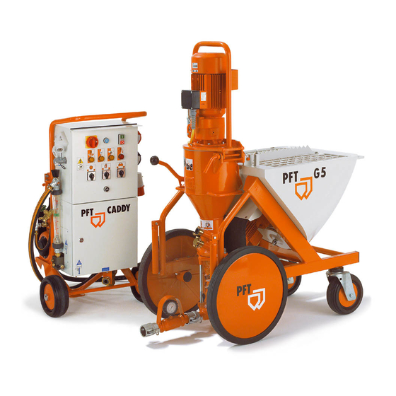
Description of functions The PFT G 5 SUPER can be loaded with bagged materials or by means of a delivery hood or injection hood. The mixing shaft and the pump are driven by a geared motor. The pump motor speed is approximately 400 rpm. -
Page 7: Dangers And Warning Symbols
PFT G 5 SUPER Operating Manual Issued 11.2008 Dangers and warning symbols The following terms and symbols are used in this manual for particularly important information: In order to make the operation of our machines as easy as possible for you, we would like to briefly inform you of the most important safety instructions. -
Page 8: Basic Safety Instructions
PFT G 5 SUPER Operating Manual Issued 11.2008 Basic safety instructions Follow all safety instructions and danger warnings on the machine. Ensure that all instructions are kept legible. Inspect the machine for visible damage and defects at least once every shift. If you notice any safety- threatening alterations to the machine or its operating behaviour, stop the machine immediately and notify your supervisor. -
Page 9: Basic Safety Instructions
PFT G 5 SUPER Operating Manual Issued 11.2008 Basic safety instructions NOTE: Special information for running the machine efficiently. WARNING! Special instructions, regulations and restrictions for the prevention of damage. WARNING! The machine should only be used if it is in flawless technical condition and in compliance with the regulations. - Page 10 PFT G 5 SUPER Operating Manual Issued 11.2008 WARNING! It is prohibited to use the machine in environments at risk of explosion. WARNING! The machine must always be in perfect condition and used in accordance with these instructions and under observation of the safety instructions and danger warnings.
-
Page 11: Signs
PFT G 5 SUPER Operating Manual Issued 11.2008 Signs The following symbols and notices are located in the work area. They refer to the immediate vicinity in which they are attached. WARNING! Danger of injury due to illegible symbols! Over the course of time, stickers and signs can become dirty or through other means unreadable. - Page 12 PFT G 5 SUPER Operating Manual Issued 11.2008 Danger point Warning of a danger point in work areas. Protective gloves for protecting hands from friction, scraping, punctures or deep injuries as well as from contact with hot surfaces. Observe the operating manual Only use the designated object after having read the operating manual.
-
Page 13: Overview Of G 5 Super: Ltem Number 00 00 84 05
PFT G 5 SUPER Operating Manual Issued 11.2008 Overview of G 5 SUPER: ltem number 00 00 84 05 1. Motor Connection Cable 2. Motor Flange 3. Pump Motor ZF 38 5,5KW 400U/min. 4. Star Wheel 5. Protection Grill + Sack Opener 6. -
Page 14: Overview Of Caddy G 5 Super: Ltem Number 00 00 82 15
PFT G 5 SUPER Operating Manual Issued 11.2008 Overview of CADDY G 5 SUPER: ltem number 00 00 82 15 1. Controll Box G 5 SUPER 2. Socket for Mains 32A 3. Housing for manifold G 5 SUPER Water Connection from Mains or Tank 5. -
Page 15: Overview Of Control Box G 5 Super: Ltem Number 00 00 71 34
PFT G 5 SUPER Operating Manual Issued 11.2008 Overview of control box G 5 SUPER: ltem number 00 00 71 34 1. Display Lamp: Direction of Rotation 2. Main Reversing Switch 3. Display Lamp: Water Pressure 4. Blue Switch: Pump Motor:Reverse 5. -
Page 16: Overview Of Water / Air Manifold
PFT G 5 SUPER Operating Manual Issued 11.2008 Overview of water / air manifold 1. Air from Compressor 2. Air-Pressure Saftey Switch 3. Compressor Switch 4. Air to Spraying Gun 5. High Pressure Pump AV 3 6. Water Saftey Switch 7. -
Page 17: Technical Specifications
PFT G 5 SUPER Operating Manual Issued 11.2008 Technical Specifications Description PFT G 5 SUPER Ltem number 00 00 79 40 400V Drive 50Hz Pump motor 5,5 kW Star wheel motor 0,75 kW Pump motor Ca.400 rpm Star wheel motor Ca. -
Page 18: Caddy Icons
PFT G 5 SUPER Operating Manual Issued 11.2008 Caddy Icons Drives Faults Star Wheelr Motor Saftey Switch off No Material Water Pump Compressor No Water Pressure Vibrator Wrong Direction Instructions At Subzero Temperatures empty all water Manual Operation Do not insert hand into... -
Page 19: Settings
PFT G 5 SUPER Operating Manual Issued 11.2008 Settings Safty switch Machine on Machine off Water 2,2 bar 1,9 bar 1,5 bar 1,9 bar Compressor 2,5 bar 3,1 bar Compressor Safety Valve Compressor on Compressor off Compressor 2,5 bar 3,1 bar... -
Page 20: Mortar Pressure
New pump components with a conveying hose of 10 m should attain a conveying pressure of approx. 30 bar and maintain a back pressure of approx. 2/3, before and after the first spraying. We recommend using the PFT pressure tester with coupling and outlet tap to monitor the backpressure: A new rotor and new stator need to be run in;... -
Page 21: Checking The Conveying Pressure And Back Pressure
PFT G 5 SUPER Operating Manual Issued 11.2008 The mixer pump PFT G 5 c FU is standardly equipped with the pump system TWISTER D6-3. The rotor and stator are subject to wear and must be checked regularly. Checking the conveying pressure and back pressure Connect a 10 m conveying hose. -
Page 22: Pump System Adjustable
PFT G 5 SUPER Operating Manual Issued 11.2008 To avoid machine breakdowns and excessive wear and tear of the pump motor, mixing shaft and pump always use ORIGINAL PFT parts such as: • PFT-Rotore • PFT-Stators • PFT-Mixing Shafts •... -
Page 23: Start-Up
The protective grille should not be removed during operation or while preparing the machine. We recommend the use of PFT power cable 5x4,0 mm², 50m with CEE plug and coupling (Item No. 20 42 39 00). Before the CADDY has power supply, see to it that : Main reversing switch (1) is switched off (Position “0“, lockable). - Page 24 Follow these instructions: Main reversing switch should be on position I If red lamp lights up (change direction of rotation), PFT G 5 SUPER will not turn on. Change direction of rotation at main reversing switch. If the direction of rotation is wrong, follow these instructions: You can lock the main reversing switch by pushing the direction plate either to the right or to the left.
-
Page 25: Setting The Water Factor
PFT G 5 SUPER Operating Manual Issued 11.2008 Press water flow button (1) (water pump should be running). Set approximate amount of water with needle valve (2). Setting the water factor Adjust the expected water volume on the needle valve (2). - Page 26 PFT G 5 SUPER Operating Manual Issued 11.2008 “HAND” (Manual Operation) The star wheel always runs when the machine is connected and switched on. Material can be added to the mixing chamber in this position when the pump is not running. This is called pre-wetting. It is advisable to pre-wet in the case of heavy materials or materials bonded with dispersion agents.
- Page 27 PFT G 5 SUPER Operating Manual Issued 11.2008 Press red pressure button (off). Machine stops. Connect air hose to air manifold and spraying gun. Switch on compressor. Connect all necessary mortar hoses with each other. Flush with water to prevent clogging. Do not allow water to remain in the hoses. Use transition adaptor (in tool kit): see page 413 for more information.
- Page 28 PFT G 5 SUPER Operating Manual Issued 11.2008 You can switch the machine on or off by either opening or shutting the air tap on the spraying gun. NOTE: While working without air supply (e.g. pumping floor screed), the machine is switched on and off by a 42 V remote control.
-
Page 29: Procedures At The End Of Work And Cleaning
PFT G 5 SUPER Operating Manual Issued 11.2008 Procedures at the End of Work and Cleaning WARNING! Before dismantling the rotor/stator pump or opening the motor flange make sure the pump and hoses are depressurized. Watch the reading on the mortar pressure gauge. - Page 30 PFT G 5 SUPER Operating Manual Issued 11.2008 Insert cleaning shaft and mixing tube cleaner with scrapers facing down. Shut motor flange and lock snaps, connect 5-pin plug on CADDY. Press green button (on), run for approx. 5 - 10 secs. until mixing tube is clean.
-
Page 31: Getting Rid Of Hose Blocks
PFT G 5 SUPER Operating Manual Issued 11.2008 Getting Rid of Hose Blocks In accordance with safety regulations of the Builder’s Guild, all personnel that clear hose blocks should wear safety goggles. Take proper precautions to stand far away from the machine to avoid injury through discharged mortar. -
Page 32: Measures For Water Supply Failure
PFT G 5 SUPER Operating Manual Issued 11.2008 Release tie rods, remove pump. Press the rotor out of the stator and clean it thoroughly. Clean pressure flange or after mixer (ROTOMIX or ROTOQUIRL).Clean mixing zone and mixing shaft with water and a trowel. - Page 33 PFT G 5 SUPER Operating Manual Issued 11.2008 Switch on compressor. Press water flow button. Compressed air will now blow water out of the manifold! (at 1,5 bar approx. for 1 minute). Swivel the entire pumping unit upwards and empty the mixing pump.
-
Page 34: Transport
Issued 11.2008 Transport First disconnect mains, then all other power connections. Remove water connections. The PFT G 5 SUPER consists of three modules (CADDY, mixing tube and material hopper) that can be transported individually. Disassemble mixing tube, if necessary WARNING! Depressurize all hoses before disconnecting them. -
Page 35: Accessories
PFT Injection Hood for the G 5 (Item No. 00 04 43 34) The PFT injection hood fills dry mortar in the PFT G 5 SUPER with the help of the SILOMAT. When the G 5 SUPER hopper is empty, the machine stops working. -
Page 36: Fault - Cause - Remedy
PFT G 5 SUPER Operating Manual Issued 11.2008 Fault – Cause – Remedy Remedy Fault Cause Machine does not start! Water Check water supply Water pressure too low Clean dirt filters Gauge shows less than 2,2 bar Switch on water pump... - Page 37 “Thick/thin“ - Water safety switch not adjusted or faulty? minute. Return slowly to normal setting. - Mixing shaft faulty, not an original PFT Readjust or replace pump mixing shaft? components with original parts. - Pressure reducing valve not adjusted or...
-
Page 38: Spare Parts List For Chassis G 5 Super: Part No. 00008223
PFT G 5 SUPER Operating Manual Issued 11.2008 Spare parts list for chassis G 5 SUPER: part no. 00008223 Knauf PFT GmbH & Co.KG... - Page 39 PFT G 5 SUPER Operating Manual Issued 11.2008 Ltem. Qty. Part no. Description 00 00 82 23 Chassis G 5 cpl. RAL2004 00 07 27 90 Star wheel ring nut M 24 galv. 00 04 89 43 Star wheel G 5 pressed cpl. RAL 2004 00 04 64 73 Star wheel G 5 pressed RAL2004 20 10 18 10 Star wheel fixing disc galv.
-
Page 40: Spare Parts List Geard Motor / Mixing Tube
PFT G 5 SUPER Operating Manual Issued 11.2008 Spare parts list geard motor / mixing tube Knauf PFT GmbH & Co.KG... - Page 41 PFT G 5 SUPER Operating Manual Issued 11.2008 Ltem. Qty Part no. Description 00 00 83 63 Motor connection cable 2.5m CEE plug 7 x 16 A 6 h red loop 5 mm 20 42 88 00 Plug CEE 7 x 16 A 6 h red no. 742 00 04 67 95 Geared motor ZF 38 5.5 kW 400 rpm with inclination switch RAL 2004...
-
Page 42: Spare Parts List Pump Unit / Mortar Pressure Gauge
PFT G 5 SUPER Operating Manual Issued 11.2008 Spare parts list pump unit / mortar pressure gauge Knauf PFT GmbH & Co.KG... - Page 43 PFT G 5 SUPER Operating Manual Issued 11.2008 Ltem. Qty Part no. Description 00 08 94 32 Suction flange D-pumps with O-Ring L 200 galv. 20 10 42 30 O-ring 117 x 5 for suction flange 00 08 94 31 Suction flange D-pump for o-ring L=200 galvanic yellow galv.
-
Page 44: Spare Parts List Chassis Caddy, Compressor K2N And Manifold Box
PFT G 5 SUPER Operating Manual Issued 11.2008 Spare parts list chassis caddy, compressor K2N and manifold box Knauf PFT GmbH & Co.KG... - Page 45 PFT G 5 SUPER Operating Manual Issued 11.2008 Ltem. Qty Part no. Description 00 00 82 18 Chassis CADDY G 5 RAL2004 00 00 83 87 Rubber guard for CADDY G 5 00 00 83 88 Clamping strip for rubber guard CADDY G5 RAL2004 20 20 20 00 EWO coupling female 1/4"...
-
Page 46: Spare Parts List Water Manifold G 5 Super: Part No. 00008260
PFT G 5 SUPER Operating Manual Issued 11.2008 Spare parts list water manifold G 5 SUPER: part no. 00008260 Knauf PFT GmbH & Co.KG... - Page 47 PFT G 5 SUPER Operating Manual Issued 11.2008 Ltem. Qty Part no. Description 00 00 82 60 Water manifold G 5 kpl. RAL2004 20 20 36 21 Angle 3/4" int. thread 1/2"int. thread no. 90 galv. 20 20 36 10 Angle 1/2" int. thread - ext. thread no. 92 galv.
- Page 48 PFT G 5 SUPER Operating Manual Issued 11.2008 Knauf PFT GmbH & Co.KG...
- Page 49 PFT G 5 SUPER Operating Manual Issued 11.2008 Ltem. Qty Part no. Description 20 19 03 20 Tap 3/8" ext. thread with socket 10 mm 20 21 36 12 Water-/air hose 1/2" x 500 mm 00 01 14 92 Socket 1/2" x 80 no. 536 galv.
-
Page 50: Spare Parts List Air Manifold G 5 Super: Part No. 00008261
PFT G 5 SUPER Operating Manual Issued 11.2008 Spare parts list air manifold G 5 SUPER: part no. 00008261 Knauf PFT GmbH & Co.KG... - Page 51 PFT G 5 SUPER Operating Manual Issued 11.2008 Ltem. Qty Part no. Description 00 00 82 61 Air manifold for G 5 20 20 36 03 Angle 3/8" int. thread no. 90 galv. 20 20 21 01 EWO coupling male 3/8" ext. thread 20 19 04 00 Hose screw joint 3/8"...
-
Page 52: Sare Parts List Control Box External: Part No. 00007134
PFT G 5 SUPER Operating Manual Issued 11.2008 Sare parts list control box external: part no. 00007134 Knauf PFT GmbH & Co.KG... - Page 53 Ltem. Qty Part no. Description 00 00 71 34 Control box G 5 SUPER 00 03 62 49 Lock for control box (double bit) 20 44 45 00 Key for control box 20 42 51 00 Panel mounted housing with plug CEE 5 x 32 A 6 h red no. 391...
-
Page 54: Spare Parts List Control Box Internal: Part No. 00007134
PFT G 5 SUPER Operating Manual Issued 11.2008 Spare parts list control box internal: part no. 00007134 Knauf PFT GmbH & Co.KG... - Page 55 Ltem. Qty Part no. Description 00 02 21 14 Housing for control box G 5 SUPER RAL9002 STRUKTUR 00 04 31 12 Door G 5 SUPER RAL9002 STRUKTUR 20 44 81 20 Contact relay 42 V 2 dispensers Time relay 42 V 1.8-180 sec. 1 closer/1opener 1 closer (immediate contact) 1...
-
Page 56: List Of Spraying Guns, Hoses, Tool Kits And Spraying Caps
PFT G 5 SUPER Operating Manual Issued 11.2008 List of spraying guns, hoses, tool kits and spraying caps Knauf PFT GmbH & Co.KG... - Page 57 PFT G 5 SUPER Operating Manual Issued 11.2008 Ltem. Qty Part no. Description 20 19 00 02 Spraying gun 25mm ID 24, cap 14 mm 00 06 23 83 Spraying cap S 14 mm black 20 19 10 00 Spraying cap 16 mm (packing unit = 10 pieces) 00 02 16 66 Tool kit mixing pump / conveying pump 20 21 10 03 Water-/air hose 1/2"...
-
Page 58: Circuit Diagramm
PFT G 5 SUPER Operating Manual Issued 11.2008 Circuit Diagramm Knauf PFT GmbH & Co.KG... - Page 59 PFT G 5 SUPER Operating Manual Issued 11.2008 Circuit Diagramm Knauf PFT GmbH & Co.KG...
- Page 60 PFT G 5 SUPER Operating Manual Issued 11.2008 Circuit Diagramm Knauf PFT GmbH & Co.KG...
- Page 61 PFT G 5 SUPER Operating Manual Issued 11.2008 Circuit Diagramm Knauf PFT GmbH & Co.KG...
-
Page 62: Check List For Annual Inspection By Specialists (Master Copy)
PFT G 5 SUPER Operating Manual Issued 11.2008 Check list for annual inspection by specialists (master copy) This inspection must be carried out once a year by a specialist in accordance with BGR 183 (German Association for Health and Safety at Work). The machine and control box receive an inspection label as verification of this inspection. -
Page 63: Notes
PFT G 5 SUPER Operating Manual Issued 11.2008 Notes: Knauf PFT GmbH & Co.KG... - Page 64 PFT G 5 SUPER Operating Manual Issued 11.2008 WE KEEP THINGS MOVING Knauf PFT GmbH & Co. KG Postfach 60 97343 Iphofen Einersheimer Straße 53 97346 Iphofen Germany Phone +49 9323 31-760 Fax +49 9323 31-770 Technical assistance hotline +49 9323 31-1818 info@pft-iphofen.de...
Need help?
Do you have a question about the G 5 SUPER and is the answer not in the manual?
Questions and answers