
Related Manuals for Telit Wireless Solutions LM940


Summary of Contents for Telit Wireless Solutions LM940
- Page 1 LM940 Translation Board HW Design Guide 1VV0301384 Rev. 0 – 6/3/2021 Telit Technical Documentation...
-
Page 2: Applicability Table
LM940 TLB HW Design Guide APPLICABILITY TABLE PRODUCTS LM940, 1.0 LM940, 2.0 1VV0301384 Rev. 0 Page 2 of 24 6/3/2021 [Disclaimer]... -
Page 3: Table Of Contents
LM940 TLB HW Design Guide CONTENTS APPLICABILITY TABLE CONTENTS INTRODUCTION Scope Related Documents GENERAL PRODUCT DESCRIPTION TLB View LPM Mode Antenna ports Guidance of Evaluation Board COMPONENT ASSEMBLY DIAGRAM SCHEMATICS ACRONYMS DOCUMENT HISTORY 1VV0301384 Rev. 0 Page 3 of 24... -
Page 4: Introduction
LM940 TLB HW Design Guide 1. INTRODUCTION Scope The scope of this document is to describe the LM940 TLB which is part of complete LM940 Development Kit (Dev-Kit) Related Documents • LM940 Hardware User Guide, 1VV301352 • Generic Evaluation Board Hardware User Guide, 1VV0301249 •... -
Page 5: General Product Description
Below the module, the bottom plane PCB solder-mask is cutout in order to optimally mount/attach a heatsink aiming to cool the module. The board is designed to accommodate modules according to the LM940 MINI PCIE (50.95 x 30.00 x 2.70mm, +/- 0.15 mm tolerance and 52 pins) updated pin mapping. -
Page 6: Tlb View
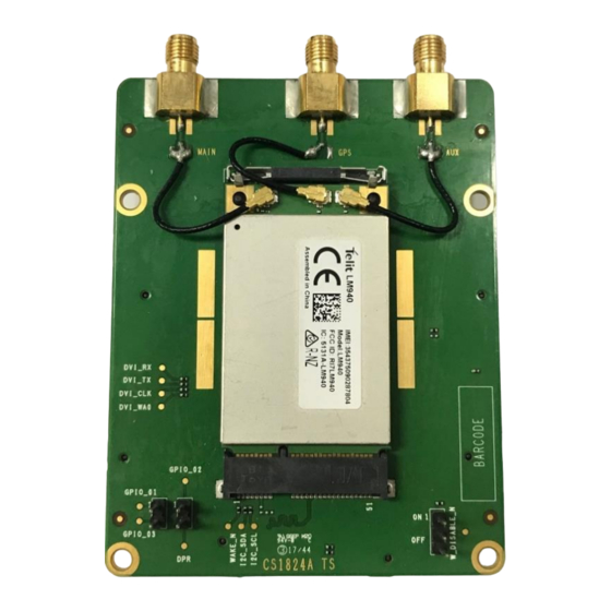
LM940 TLB HW Design Guide TLB View The below pictures show the TLB top and bottom view. LM940 1.0 TLB Top View LM940 1.0 TLB Bottom View 1VV0301384 Rev. 0 Page 6 of 24 6/3/2021 [Disclaimer]... - Page 7 LM940 TLB HW Design Guide LM940 2.0 TLB Top View LM940 2.0 TLB Bottom View 1VV0301384 Rev. 0 Page 7 of 24 6/3/2021 [Disclaimer]...
-
Page 8: Lpm Mode
This section contains how to switch to LPM mode by means of a header jumper. Jumper Header Description 2 – 3: Low LPM mode The W_DISABLE_N signal is provided to trigger the LM940 to switch to Low W_DISABLE_N Power Mode (also known as “Airplane Mode”). 1VV0301384 Rev. 0 Page 8 of 24... -
Page 9: Antenna Ports
LM940 TLB HW Design Guide Antenna ports LM940 1.0 TLB 1VV0301384 Rev. 0 Page 9 of 24 6/3/2021 [Disclaimer]... - Page 10 LM940 TLB HW Design Guide LM940 2.0 TLB Note: For more detailed information regarding Antenna ports, please refer to 1VV0301352 LM940 HW Design Guide, Chapter 7.1 Antenna requirements. 1VV0301384 Rev. 0 Page 10 of 24 6/3/2021 [Disclaimer]...
-
Page 11: Guidance Of Evaluation Board
LM940 TLB HW Design Guide Evaluation Board Connections Note: For more detailed information regarding power supply source selection, please refer to 1VV0301249 Telit Evaluation Board (EVB) HW User Guide, Chapter 7.1 Supply Source Selection. 1VV0301384 Rev. 0 Page 11 of 24... - Page 12 LM940 TLB HW Design Guide 1VV0301384 Rev. 0 Page 12 of 24 6/3/2021 [Disclaimer]...
- Page 13 2 seconds AT Commands / DATA port Connect the USB 2.0/3.0 cable to a Windows or Linux PC only after installing the appropriate drivers. Refer to the LM940 SW User Guide for details 1VV0301384 Rev. 0 Page 13 of 24 6/3/2021...
-
Page 14: Component Assembly Diagram
LM940 TLB HW Design Guide 3. COMPONENT ASSEMBLY DIAGRAM Searchable Layout LM940 1.0 Component Diagram TOP View 1VV0301384 Rev. 0 Page 14 of 24 6/3/2021 [Disclaimer]... - Page 15 LM940 TLB HW Design Guide LM940 1.0 Component Diagram BOTTOM View 1VV0301384 Rev. 0 Page 15 of 24 6/3/2021 [Disclaimer]...
- Page 16 LM940 TLB HW Design Guide LM940 2.0 Component Diagram TOP View 1VV0301384 Rev. 0 Page 16 of 24 6/3/2021 [Disclaimer]...
- Page 17 LM940 TLB HW Design Guide LM940 2.0 Component Diagram BOTTOM View 1VV0301384 Rev. 0 Page 17 of 24 6/3/2021 [Disclaimer]...
-
Page 18: Schematics
LM940 TLB HW Design Guide 4. SCHEMATICS Searchable PDF LM940 1.0 TLB 1VV0301384 Rev. 0 Page 18 of 24 6/3/2021 [Disclaimer]... - Page 19 LM940 TLB HW Design Guide 1VV0301384 Rev. 0 Page 19 of 24 6/3/2021 [Disclaimer]...
- Page 20 LM940 TLB HW Design Guide LM940 2.0 TLB 1VV0301384 Rev. 0 Page 20 of 24 6/3/2021 [Disclaimer]...
- Page 21 LM940 TLB HW Design Guide Note: For a higher resolution version of the schematic diagram, please contact Telit technical support as below. • TS-EMEA@telit.com • TS-AMERICAS@telit.com • TS-APAC@telit.com • TS-SRD@telit.com 1VV0301384 Rev. 0 Page 21 of 24 6/3/2021 [Disclaimer]...
-
Page 22: Acronyms
LM940 TLB HW Design Guide 5. ACRONYMS Evaluation Board Translation Board Board to Board Low Power Mode 1VV0301384 Rev. 0 Page 22 of 24 6/3/2021 [Disclaimer]... -
Page 23: Document History
LM940 TLB HW Design Guide 6. DOCUMENT HISTORY Revision Date Changes 2021-06-03 First released Mod.0818 Rev.1 2020-10 1VV0301384 Rev. 0 Page 23 of 24 6/3/2021 [Disclaimer]...
Need help?
Do you have a question about the LM940 and is the answer not in the manual?
Questions and answers