Table of Contents
Advertisement
Available languages
Available languages
Quick Links
SMP 7600R USER MANUAL
SpaceMaster Series
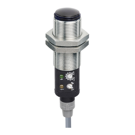
Photoelectric diffuse proximity sensors
Product Data
Electrical Data
Supply Voltage
Voltage ripple
Reverse polarity protected
Short circuit protected
Current consumption
Max. output load
Light source
Spot size
Environmental Data
Temperature, operation
Sealing class
Approvals
Available Models
Supply
Model
Voltage
Diffuse
SMP 7600R
10-30 V dc
Proximity
* Note: Measured against matt white A4 paper.
Illustration
Connection
Wiring Diagrams
SMP 7600R
Load as NPN
Connection Wires/Pins
Cable
Supply +
Brown
Supply -
Blue
Output
White
Output
Black
-
Website: www.telcosensors.com
E-Mail:
info@telcosensors.com
Made in Denmark
10-30 V dc
+/- 15%
Yes
Yes
20 mA
120 mA / 30 V dc
Visible red light (620 nm)
4 x 4 cm @ 35 cm range
-20 to +60 ºC
IP 67
Sensing
Output
Output Mode
Range
35 cm,
NPN/PNP
Light/dark
adjustable*
SMP 7600R
Load as PNP
4 pin, M8 plug
4 pin, M12 plug
Pin 1
Pin 1
Pin 3
Pin 3
Pin 2
Pin 2
Pin 4
Pin 4
Sensor plug
Sensor plug
!
This device is not to be used for Personnel Protection in Machine
Guarding Safety applications. This device does not include the self-
checking redundant circuitry necessary to allow its use in personnel
machine guarding stand-alone safety applications.
EN
Mounting & Installation
Mounting & Installation
1
Position the sensor pointing at the target object.
Align by moving sensor horizontally and vertically until the output changes when the
2
target object is present (refer to Output Logic table).
Fasten the sensor securely using the enclosed locking nuts and/or a mounting bracket.
3
Avoid acute angles on cable close to sensor.
Adjustments
Output Mode Selection
The output mode can be selected via an integral light/dark switch. Refer to Output Logic table
for output mode reference.
Enables the output to be active
Light Operated (N.O.)
when there is an object present.
Enables the output to be inactive
Dark Operated (N.C.)
when there is an object present.
Output Logic
Detection
Object present
Object absent
Sensitivity Adjustment
Maximum sensitivity can be used for most applications and is advised for applications with
contaminated environments. Increase the sensitivity to maximum by turning the potentiometer
to full clockwise position.
Sensitivity adjustment may be required in applications where objects to be detected have
highly reflective, dark or textured surfaces and/or applications where a background is present.
Proceed with the following steps:
Start with the sensitivity at minimum by turning the potentiometer to full counter
1
clockwise position.
2
Select target object with the smallest dimensions and least reflective surface.
3
Place target object in front of sensor.
Increase the sensitivity by turning the potentiometer clockwise until the target object
4
is detected and the output status changes (Position 1). If the output has not
changed, attempt to move sensor closer to target object and repeat procedure.
If there is a background proceed to step 7.1. If there is no background proceed to
5
step 6.
Turn the potentiometer clockwise to a position midway between Position 1 and
6
maximum clockwise position.
Remove target object. If the output changes, proceed to step 7.2. If the output has
7.1
not changed, a background is detected. Proceed to step 7.4
Turn the potentiometer clockwise until the output status changed (Position 2). A
7.2
background is now detected.
Turn the potentiometer counter clockwise to a position midway between Position 1
7.3
and Position 2.
If the background is still detected and the output has not changed, attempt to angle
7.4
the sensor in relation to the plane of the background. Then repeat procedure from
step 1.
Warning
tel
Turn switch to full clockwise
position
Turn switch to full counter
clockwise position
Output mode
Output status
Dark operated (N.C.)
Open
Light operated (N.O.)
Closed
Light operated (N.O.)
Open
Dark operated (N.C.)
Closed
V 1.0 Part Number: 0666220902
Telco A/S reserves the right to make changes without prior notice
Yellow LED
Off
On
Off
On
March 2020 edition
Advertisement
Table of Contents

Related Manuals for Telco Sensors SpaceMaster Series


Summary of Contents for Telco Sensors SpaceMaster Series
- Page 1 SMP 7600R USER MANUAL SpaceMaster Series Photoelectric diffuse proximity sensors Product Data Mounting & Installation Electrical Data Mounting & Installation Supply Voltage 10-30 V dc Position the sensor pointing at the target object. Voltage ripple +/- 15% Reverse polarity protected...
- Page 2 SMP 7600R Bedienungsanleitung SpaceMaster Serie Reflexionslichttaster Produktinformation Befestigung & Installation Technische Daten Befestigung & Installation Betriebsspannung 10-30 VDC Der Sensor schaut auf das zu erfassene Objekt Restwelligkeit +/- 15% Verpolungsschutz Bewegen Sie den Sensor horizontal und vertikal bei vorhandendem Objekt, bis der Kurzschlussschutz Ausgang sich ändert.
- Page 3 SMP 7600R – MANUEL D’UTILISATEUR La série SpaceMaster Détecteur photoélectrique en proximité Caractéristique technique Montage & Installation Montage & Installation Caractéristique électrique Alimentation 10-30 V dc Placez le détecteur se dirigeant à l’objet à détecter. Ondulation résiduelle +/- 15% Protection contre les inversions de polarités Alignez le détecteur en déplaçant horizontalement puis verticalement jusqu’à...
- Page 4 SMP 7600R - MANUAL DE USUARIO Serie SpaceMaster Fotocélula con salida transistor incorporada Modo Autoreflexivo (Diffuse Proximity) Especificaciones Técnicas Montaje Datos Eléctricos Montaje Tensión de alimentación 10-30 V dc Sitúe el sensor dirigido al objeto a detectar. Tolerancia +/- 15% Protec.
Need help?
Do you have a question about the SpaceMaster Series and is the answer not in the manual?
Questions and answers