Advertisement
Quick Links
SMRR 7000-IO - USER MANUAL
SpaceMaster Series
Photoelectric retro-reflective sensors with IO-link
Product Data
Electrical Data
Supply Voltage
Voltage ripple
Current consumption
Max. output load
Reverse polarity protected
Short circuit protected
Environmental Data
Temperature, operation
Sealing class
Approvals
Available Models
Model
SMRR 7400 IO xx x
Diffuse
Proximity
SMRR 7500 IO xx x
* Note: Measured against the Ø85 mm retro-reflector.
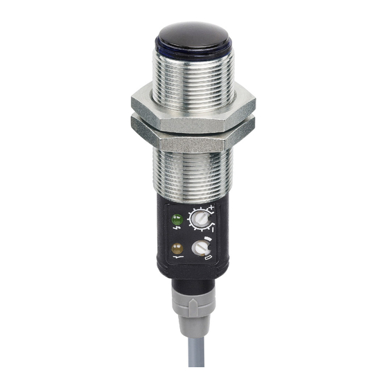
Illustration
Connection
Wiring Diagrams
Connection Pins
Supply +
Brown
Supply -
Blue
IO-Link
Black
Control/Output
White
Website: www.telcosensors.com
E-Mail:
info@telcosensors.com
Made in Denmark
10 – 30 V dc
+/- 15%
30 mA
200 mA / 30 V dc
Yes
Yes
-20 to +60 ºC
IP 67
Supply
Output
Output
Voltage
Mode
IO-Link/NPN
10-30 V
Light/dark
dc
IO-Link/PNP
SMRR 7400 IO
SMRR 7500 IO
4 pin, M8 plug
4 pin, M12 plug
Pin 1
Pin 1
Pin 3
Pin 3
Pin 4
Pin 4
Pin 2
Pin 2
Sensor plug
Sensor plug
!
This device is not to be used for Personnel Protection in Machine
Guarding Safety applications. This device does not include the self-
checking redundant circuitry necessary to allow its use in personnel
machine guarding stand-alone safety applications.
EN
Mounting & Installation
Mounting & Installation
1
Position the sensor pointing at the target object.
Align by moving sensor horizontally and vertically until the output changes when the
2
target object is present (refer to Output Logic table).
Fasten the sensor securely using the enclosed locking nuts and/or a mounting bracket.
3
Avoid acute angles on cable close to sensor.
Adjustments
General
Sensitivity and output mode can be adjusted using the potentiometers or with the IO-Link.
Sensing
The IO-Link allows the user to setup and read several functions and parameters. Please refer to
Range
"SMRR and PC connection" on the following page.
Output Mode Selection
0 – 3m*
The output mode can be selected via an integral light/dark switch, or via IO-Link. Refer to Output
Logic table for output mode reference. Note that the NPN output is closed when IO-Link/push-
pull is low and the yellow output LED is off.
Light Operated (N.C.)
Dark Operated (N.O.)
Output Logic
Detection
Object present
Object absent
Sensitivity Adjustment
Maximum sensitivity can be used for most applications and is advised for applications with
contaminated environments. The sensitivity can be adjusted on the potentiometer (factory
default active) or via IO-Link.
Sensitivity adjustment may be required in applications where objects to be detected have
highly reflective, dark or textured surfaces and/or applications where a background is present.
This can be achieved manually or via IO-Link.
Load as NPN
For sensitivity adjustment, proceed with the following steps:
Start with the sensitivity at minimum by turning the potentiometer to full counter
1
clockwise position, or by setting the Gain value to 255.
2
Select target object with the smallest dimensions and most translucent surface.
Place target object between the sensor and retro-reflector. If the output status
3
changes, adjustment is not required. If the output has not changed proceed to step
4.
Decrease the sensitivity by turning the potentiometer counter clockwise or decrease
the Gain value to a lower value until the output changes.
4
If the output has not changed, attempt to move the sensor and retro-reflector further
Load as PNP
apart or angle the sensor/retro-reflector. Then repeat procedure from step 1.
Alternatively, remove any object and press teach-gain button using IO-link.
5
Remove target object. Check the output status has changed.
Warning
Turn switch to full clockwise
position, or set:
Enables the output to be inactive
- Overwrite light operated = true
when there is an object present.
- Light operated = true
in the Parameters tab.
Turn switch to full counter
clockwise position, or set:
Enables the output to be active
- Overwrite light operated = true
when there is an object present.
- Light operated = false
in the Parameters tab.
Output status
Output mode
IO-Link
PNP
Light operated
Low
Open
(N.C.)
Dark operated
High
Closed
(N.O.)
Light operated
High
Closed
(N.C.)
Dark operated
Low
Open
(N.O.)
V 1.0 Part Number: L40-0666220939
Telco A/S reserves the right to make changes without prior notice
tel
Yellow LED
NPN
Closed
Off
Open
On
Open
On
Closed
Off
October 2021 edition
Advertisement

Related Manuals for Telco Sensors SpaceMaster Series


Summary of Contents for Telco Sensors SpaceMaster Series
- Page 1 SMRR 7000-IO - USER MANUAL SpaceMaster Series Photoelectric retro-reflective sensors with IO-link Product Data Mounting & Installation Electrical Data Mounting & Installation Supply Voltage 10 – 30 V dc Position the sensor pointing at the target object. Voltage ripple +/- 15%...
- Page 2 Connect the TMG-USB IO-Link Master USB-adapter to the USB-port of the PC and to the cable of the SMRR. Download the IO-Link Device Tool software and the SMRR-IODD file from the Telco Sensors website in https://www.telcosensors.com/downloads selecting Software in Document type section.
- Page 3 SMRR 7000 IO USER MANUAL SpaceMaster Series Photoelectric retro-reflective sensors with IO-link Parameters On the Parameter tab, the parameters of the sensor can be set up or modified. General settings SMRR: System Command - Restore Factory Settings Restores all user-settings to default values.
- Page 4 SMRR 7000 IO USER MANUAL SpaceMaster Series Photoelectric retro-reflective sensors with IO-link Process Data Process data SMRR: Output Status on the output. Light Operated Status on the light operated selection. Gain Status on the gain value. Identification On the identification tab, general information about the sensor is displayed.
Need help?
Do you have a question about the SpaceMaster Series and is the answer not in the manual?
Questions and answers