
Related Manuals for Wiedenmann TERRA GROOM


Summary of Contents for Wiedenmann TERRA GROOM
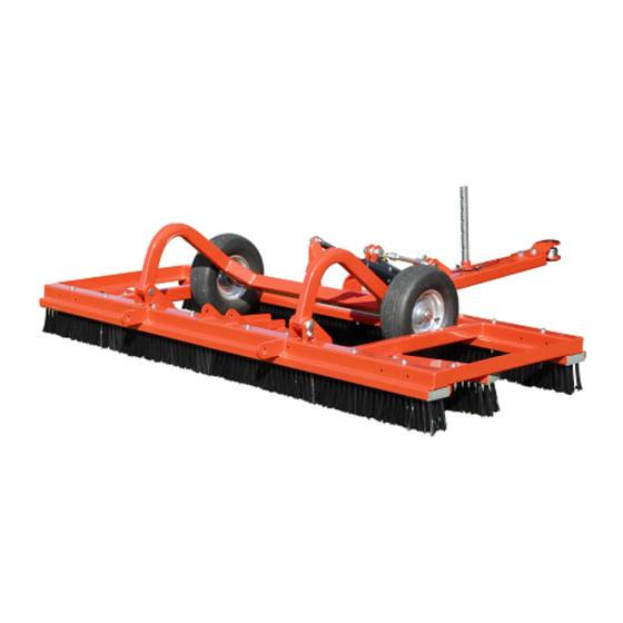
- Page 1 Translation of original Operating Instructions Sand brush TERRA GROOM 515.002 From equipment I.D. No. : 515 AA 1001 Status : January 2012 515 99 01...
- Page 2 All information, illustrations and specifications in these Operating Instructions are based on the latest information available at the time of publication. We reserve the right to make design changes at any time without prior notification...
- Page 3 All information, illustrations and specifications in these Operating Instructions are based on the latest information available at the time of publication. We reserve the right to make design changes at any time without prior notification...
- Page 4 Preface READ THESE OPERATING INSTRUCTIONS CAREFULLY to familiarise yourself with the correct way to operate and service your machine, and to prevent personal injury or damage to the machine. These operating instructions and the adhesive safety signs on your machine can also be obtained in other languages (your dealer can order these for you).
-
Page 5: Table Of Contents
Mounting the magnetic bar......18+19 2.10. Mounting the decompaction brush set....20 3.0. Transport..........21+22 3.1. General information....... 21 3.2. Transport of the TERRA GROOM...... 22 4.0. Connecting to the tractor........23-25 4.1. General information....... 23 4.2. Mounting with three-point hitch....23 4.3. -
Page 6: Safety Measures
1.0. Safety Measures RECOGNISE WARNING SYMBOLS This symbol draws your attention to the safety instructions attached to the machine or contained in these operating instructions. It means that there is a risk of injury. Follow all recommended safety instructions as well as the accident prevention regulations. - Page 7 1.0. Safety Measures OBSERVE THE ROAD TRAFFIC REGULATIONS Always observe local road traffic regulations when using public roads. WEAR PROTECTIVE CLOTHING Wear close-fitting clothing and the appropriate safety equipment for the work at hand. Prolonged exposure to loud noise can result in impairment or loss of hearing.
- Page 8 1.0. Safety Measures STAY CLEAR OF ROTATING DRIVE SHAFTS Carelessness in the area of the rotating drive shafts can result in serious injury or even death. Always ensure that all shaft protection devices are fitted i.a.w. regulations and that the universal-joint shaft sheath tubing can turn freely.
- Page 9 1.0. Safety Measures USE SAFETY LIGHTS AND EQUIPMENT Avoid collisions with other road users. Slow moving tractors with mounted or towed equipment, and self-propelled machines on public roads pose a specific danger. Frequently check for traffic coming behind you, especially when making turns. Ensure safe traffic conditions by using hand signals or indicators.
- Page 10 1.0. Safety Measures REMOVE PAINT BEFORE WELDING OR HEATING PARTS Welding should only be carried out by persons with a relevant qualifying certificate i.a.w. EN287. Avoid the formation of toxic fumes and dust. Hazardous fumes can be generated when paint is heated due to welding, soldering, or using a welding torch.
-
Page 11: Safety Signs
1.0. Safety Measures 1.1. Adhesive Safety Signs Warning symbols Warning symbols indicating danger are attached at some important areas on the machine. The hazard is identified via a warning triangle. A second symbol informs you how the injury can be prevented by acting appropriately. -
Page 12: Safety Instructions
The driving and operational characteristics of the tractor may be influenced by the attachment of the TERRA GROOM. Always adapt your driving style to match the terrain and ground conditions. Special care should be taken when working and turning on a slope. -
Page 13: Assembly
2.0. Assembly 2.1. General Information Only carry out attachment on shut off and the PTO shaft firm, even ground. drive is switched off. For this work, please use The warning and information your personal protective signs on the machine contain equipment (PSA) such as: important information to gloves, goggles, ear... -
Page 14: Positioning The Supports
2.0. Assembly 2.3. Positioning the supports 2.3.1. Three-point hitch version Both parking supports (A) are to be secured to the square pipes of the basic unit so that no bristles are touching the ground when the machine is in the parking position. 2.4. -
Page 15: Installing The Drawbar
2.0. Assembly 2.5. Installing the drawbar Insert drawbar (A) on basic unit using locking bolt (B). To secure, screw in screw (C). Secure turnbuckle (D) on basic unit using screw (E). 2.6. Mounting electric lifting equipment for chassis Secure electro spindle (A) on chassis (C) using screw (D). -
Page 16: Install Strip Brushes
2.0. Assembly 2.7. Install strip brushes Hold the strip brushes from underneath in the guide. Manually screw in long hexagon head screws (A) with washers at the straight guides. Manually screw in short hexagon head screws (B) with washers at the offset guides. -
Page 17: Mounting The Spherical Coupling
2.0. Assembly 2.8. Mounting the spherical coupling Release fixing screws (A) and remove with the draw shackles. Secure the spherical coupling, instead of the draw shackles, on the drawbar profile using supplied screws (B). All information, illustrations and specifications in these Operating Instructions are based on the latest information available at the time of publication. -
Page 18: Mounting The Magnetic Bar
2.0. Assembly 2.9. Mounting the magnetic bar Warning Pacemakers • Magnets can influence the A defibrillator may no function of pacemakers and longer function under implanted defibrillators. certain circumstances. • Please maintain sufficient • A pacemaker may be distance to the magnets if switched to test mode and you have a cause discomfort. - Page 19 2.0. Assembly 2.9. Mounting the magnetic bar 2.9.2. In the trailed version The magnetic bar is attached to the front lugs of the basic unit. Slide the brackets of the magnetic bar onto lugs (E) and securely screw on. Remove set screw (F) for swivelling the magnetic bar.
-
Page 20: Mounting The Decompaction Brush Set
2.0. Assembly 2.10. Mounting the decompaction brush set Remove the brush strips in the front support. A washer and snap ring are required for the new installation. Place plate (A) on brush strip (B) and align with the mounting holes Hold brush strip (B) from underneath in the guide. -
Page 21: Transport
Never stand under lifted loads. There is an imminent danger to life if the load falls. Improper transport and mounting of the TERRA GROOM can result • injury to persons, • damage to property. Pay special attention to the direction of approach when lifting the machine with the transport frame. -
Page 22: Transport Of The Terra Groom
3.0. Transport 3.2. Transport of the TERRA GROOM 3.2.1. Transport Using a Forklift If the TERRA GROOM is still secured on the transport frame: • Insert the forks under the transport frame (pay attention to the direction of approach), •... -
Page 23: Connecting To The Tractor
4.0. Connecting to the Tractor 4.1. General Information CAUTION ! Switch off the engine before performing any work. The ignition key must be removed. Secure the tractor against rolling away. The following is required for attaching the machine: • Tractors with at least 9 kW (12 hp) •... -
Page 24: Mounting With Drawgear
4.0. Connecting to the Tractor 4.3. Mounting with drawbar Insert drawbar on tractor and secure. For a description of the setting, please see Chapter 6.2. If your tractor is not equipped with such a socket, please consult your dealer or have one installed by a specialist technician. -
Page 25: Ballast
4.0. Connecting to the Tractor 4.5. Ballast ATTENTION: Specifications in the Operating Instructions for the tractor must be observed. When mounting equipment at When selecting the front axle the rear, always ensure there load, ensure that the is sufficient front axle permissible axle load weight, load;... -
Page 26: General Information
(C). Insert supports (D) in the topmost bores. Secure pin (C) with spring cotter. Lower TERRA GROOM to ground. Release upper guide bar and disconnect pins (A) from three- point frame. Release lower guide bar turnbuckles and remove lower guide bar from locating pins (B) on three-point frame. -
Page 27: Removal With Three-Point Hitch
5.0. Disconnecting from the Tractor 5.3. Removal with trailer version Lower support at drawbar and secure. Disconnect plug. The mounted machine is set down in the transport position. Disconnect drawbar from tractor. All information, illustrations and specifications in these Operating Instructions are based on the latest information available at the time of publication. -
Page 28: Before Initial Operation
! travel on public roads! In addition to the information provided in these 6.2. Setting the TERRA GROOM The setting is to be realised on an even, secure surface with the machine in the mounted condition. -
Page 29: Operation
CAUTION: In the working area, the The ground must be dry for user is responsible for the the use of the Terra Groom. safety of other persons ! Use of the Terra Brush requires dry ground. In wet Avoid driving in tight... -
Page 30: Malfunctions And Troubleshooting
7.0. Operation 7.3. Malfunctions and troubleshooting CAUTION: Switch off the engine before performing any work. The ignition key must be removed. Secure the tractor against rolling away. Description Cause Remedy Chassis cannot be Safeguard on tractor Check safeguard, replace raised or lowered faulty where req. -
Page 31: Deformed Strip Brushes
7.0. Operation 7.4. Deformed strip brushes We recommend that your turn all strip brushes at certain intervals (see Chapter 8.5.). In the case of seriously bent bristles, replacement of the set is necessary. All information, illustrations and specifications in these Operating Instructions are based on the latest information available at the time of publication. -
Page 32: Maintenance
8.0. Maintenance 8.1. General Information ATTENTION : Only qualified personnel are permitted to perform maintenance, repair and disassembly tasks. Switch off the engine before performing any work. The ignition key must be removed. Apply the parking brakes to ensure the tractor does not roll away. -
Page 33: Wheels And Tyres
8.0. Maintenance 8.3. Wheels and tyres Check the air pressure regularly : 0,6 bar (9 psi) CAUTION: Serious or fatal injuries may result from explosive tyres and tyre or rim parts. Always ensure the tyre pressure is correct and do not exceed the maximum pressure stated. -
Page 34: Replacing Strip Brushes
8.0. Maintenance 8.5. Replacing strip brushes The strip brushes must always be replaced in sets. Release hexagon screws (A) Replace strip brush Screw hexagon screws (A) in manually. Align strip brushes. Firmly tighten hexagon screws. NOTE: When mounting the strip brush, always begin in the centre. -
Page 35: Disassembly / Disposal
Get detailed information about their disposal. 8.7. Unauthorised modification and spare part manufacturing • Conversion or modifications to the TERRA GROOM are only permitted after prior consultation with the manufacturer! • Original parts and accessories authorised by the manufacturer serve for your safety. -
Page 36: Equipment
9.0. Equipment 9.1. Scope of Delivery Basis unit Chassis with drawbar and electric hoist three-point linkage Brush set ( selective Operating instructions, transfer declaration with guarantee card. 9.2. Machine designs Three-point version Trailer version Basic unit Three-point frame - - - Parking support set - - - Chassis and drawbar... -
Page 37: Special Equipment
9.0. Equipment 9.3. Special equipment Spherical coupling Only for trailed version Decompaction brush set Only suitable for use on synthetic turf for the purpose of loosening the granule material Magnetic bar For picking up dangerous metal objects e.g. hairpins All information, illustrations and specifications in these Operating Instructions are based on the latest information available at the time of publication. -
Page 38: Technical Specifications
11 (15) KW (PS) Min. lifting power of tractor Operating speed km/h Terra Groom neutral Magnetic bar + 10 Decompaction brush set Max. total weight All information, illustrations and specifications in these Operating Instructions are based on the latest information available at the time of... - Page 39 10.0. Technical Specifications 10.1. Technical Data Three-point version: 515.31 All information, illustrations and specifications in these Operating Instructions are based on the latest information available at the time of publication. We reserve the right to make design changes at any time without prior notification...
- Page 40 Tyre pressure Track width Number of axles Quantity Number of wheels per axle Quantity Terra Groom neutral Magnetic bar + 10 Spherical coupling Decompaction brush set Max. total weight All information, illustrations and specifications in these Operating Instructions are based on the latest information available at the time of...
- Page 41 10.0. Technical Specifications 10.2. Technical Data Trailer version: 515.46 All information, illustrations and specifications in these Operating Instructions are based on the latest information available at the time of publication. We reserve the right to make design changes at any time without prior notification...
- Page 42 10.0. Technical Specifications 10.3. Metric bolt and cap screw torque values Property Class and Head Markings Property Class and Markings class 4.8 class 8.8 or 9.8 class 10.9 class 12.9 Size Dry ** Dry ** Dry ** Dry ** Lubricated * Lubricated * Lubricated * Lubricated *...
- Page 43 10.0. Technical Specifications 10.4. Chassis Number Enter the respective product Wiedenmann D-89192 Rammingen identification no. in the space TERRA GROOM provided below. Always quote this number when ordering spare parts or in case of warranty claims. 515.30 Veh. Id. no......
Need help?
Do you have a question about the TERRA GROOM and is the answer not in the manual?
Questions and answers