
Related Manuals for Wiedenmann Super 600


Summary of Contents for Wiedenmann Super 600
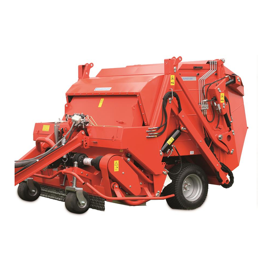
- Page 1 Translation of original Operating Instructions Lawn Maintenance Machine Super 600 275.001 From equipment I.D. No. : 10102750005142001 Status : May 2014 275 99 01...
- Page 2 All information, illustrations and specifications in these Operating Instructions are based on the latest information available at the time of publication. We reserve the right to make design changes at any time without prior notification...
- Page 3 All information, illustrations and specifications in these Operating Instructions are based on the latest information available at the time of publication. We reserve the right to make design changes at any time without prior notification...
- Page 4 Preface READ THESE OPERATING INSTRUCTIONS CAREFULLY to familiarise yourself with the correct way to operate and service your machine, and to prevent personal injury or damage to the machine. These operating instructions and the adhesive safety signs on your machine can also be obtained in other languages (your dealer can order these for you).
-
Page 5: Table Of Contents
Safety decals........12-14 1.2. Notes on safety......... 15 1.3. Safety features......... 16+17 2.0. Transport..........18-21 2.1. General Information......18 2.2. Super 600 ......19-21 transportation. 3.0. Assembly..........22-30 3.1. General Information......22 3.2. Attaching the drawbar......22 3.3. Installing the hopper gate...... 23+24 3.4. - Page 6 TABLE OF CO N T E N T S Page * * * * * * * * * * * * * * * * * * * * * * * * * * * * * * * * * * * * * * * * * * * * * * * * * * * 8.0.
-
Page 7: Safety Measures
1.0. Safety Measures RECOGNISE WARNING SYMBOLS This symbol draws your attention to the safety instructions attached to the machine or contained in these operating instructions. It means that there is a risk of injury. Follow all recommended safety instructions as well as the accident prevention regulations. -
Page 8: Safety Features
1.0. Safety Measures OBSERVE THE ROAD TRAFFIC REGULATIONS Always observe local road traffic regulations when using public roads. WEAR PROTECTIVE CLOTHING Wear close-fitting clothing and the appropriate safety equipment for the work at hand. Prolonged exposure to loud noise can result in impairment or loss of hearing. - Page 9 1.0. Safety Measures STAY CLEAR OF ROTATING DRIVE SHAFTS Carelessness in the area of the rotating drive shafts can result in serious injury or even death. Always ensure that all shaft protection devices are fitted i.a.w. regulations and that the universal-joint shaft sheath tubing can turn freely.
- Page 10 1.0. Safety Measures USE SAFETY LIGHTS AND EQUIPMENT Avoid collisions with other road users. Slow moving tractors with mounted or towed equipment, and self-propelled machines on public roads pose a specific danger. Frequently check for traffic coming behind you, especially when making turns. Ensure safe traffic conditions by using hand signals or indicators.
- Page 11 1.0. Safety Measures REMOVE PAINT BEFORE WELDING OR HEATING PARTS Welding should only be carried out by persons with a relevant qualifying certificate i.a.w. EN287. Avoid the formation of toxic fumes and dust. Hazardous fumes can be generated when paint is heated due to welding, soldering, or using a welding torch.
-
Page 12: Safety Decals
1.0. Safety Measures 1.1. Adhesive Safety Signs Warning symbols Warning symbols indicating danger are attached at some important areas on the machine. The hazard is identified via a warning triangle. A second symbol informs you how the injury can be prevented by acting appropriately. - Page 13 1.0. Safety Measures 1.1. Adhesive Safety Signs Tools Never touch the moving parts of the machine. Wait until they have come to a complete standstill. Tools for the multifunction head Never operate the multifunction head when the container is elevated. There is danger of injury from the spinning tool drum and from 275.03...
- Page 14 275.08 Perforated screen and service flap When the Super 600 is running, no persons may stand in front of the perforated screen on the rear of the machine. There is a risk of injury from thrown or flying objects.
-
Page 15: Notes On Safety
Super 600! • Familiarize yourself with all Always adapt your driving equipment and operating style to match the terrain elements and their functions and ground conditions. - Page 16 1.0. Safety Measures 1.3. Safety Equipment 1.3.1. on the machine ATTENTION DANGER! Never operate the Super 600 Serious injury by moving without safety devices. parts can result. Otherwise you expose yourself and others to great danger. Where to find safety equipment on your machine: 275.10...
- Page 17 1.0. Safety Measures 1.3. Safety Equipment 1.3.2. on the remote control ATTENTION DANGER! Lift multi-cultivation rail. Otherwise you will be exposing yourself and others to extreme danger. Serious injury by moving parts can result. Positions of the buttons: ON/OFF button – When the control unit is switched off, all valves are locked.
-
Page 18: Transport
2.0. Transport 2.1. General Information ATTENTION DANGER! • The lawn maintenance machine is delivered secured on a transport frame. • Only use fork lifts, cranes or hoisting gear with sufficient lifting capacity. • Never stand under lifted loads. There is an imminent danger to life if the load falls. -
Page 19: Super 600 Transportation
2.0. Transport 2.2. Super 600 transportation 2.2.1. Transport using a forklift If the lawn maintenance machine is still secured on the transport frame: • Insert the forks under the transport frame (pay attention to the direction of approach), • carefully lift the transport frame, •... - Page 20 2.0. Transport 2.2. Super 600 transportation 2.2.3. Mounting point for transport on a trailer Point C: 2x on the drawbar (position arrow left) on a hole in the lug on the frame (position arrow right) depending on the lashing gear...
- Page 21 2.0. Transport 2.2. Super 600 transportation 2.2.4. Transport frame During transport, the hopper gate (A) and drawbar (B) are not fitted. The hopper gate (A) is inserted at the front of the machine with special parts and secured at the top.
-
Page 22: Assembly
3.0. Assembly 3.1. General Information For this work, please use ATTENTION DANGER! your personal protective Only perform this work when equipment (PSA) such as: the machine is connected to gloves, goggles, ear the tractor. The tractor must protectors. be switched off and secured Only carry out attachment on against unintentional firm, even ground. -
Page 23: Installing The Hopper Gate
3.0. Assembly 3.3. Installing the hopper gate At least 2 persons are required for this work. Remove top part and side parts of the transport frame. Release the drawbar (A) from the transport frame. Suspend the hopper gate at the two ring screws (B) and secure. - Page 24 3.0. Assembly 3.3. Installing the hopper gate Carefully move the suspended hopper gate to the rear of the Super 600. Remove the bearing bolts (E) which support the hopper gate. Remove the bearing bolts (F) which support the hydraulic cylinder (G).
-
Page 25: Electric Connection To Battery
3.0. Assembly 3.4. Electric connection to battery Only appropriately qualified professionals may carry out the connection work. Mount 3-pin socket (A) at a suitable location in the area of the driver's seat. Install cable (B) from the battery to 3-pin socket (A). Insert flat connector (C) of line 1 in socket (A) at position (D). -
Page 26: Connecting The Control Unit
3.0. Assembly 3.5. Connecting the control unit The control unit has a 4-pin connection on its rear side to which the connection cable (A) must be connected. The control panel must be in a suitable bracket during operation. A suction cup holder is included with the machine. -
Page 27: Option: Attaching Anti-Scalp Rollers
3.0. Assembly 3.6. Option: Attaching anti-scalp rollers The anti-scalp rollers ensure that only the verticutting blades come into contact with the ground and not the flywheels. Setting the anti-scalp rollers NOTE Set the anti-scalp rollers the same on both sides. •... -
Page 28: Option: Attaching Golf Course Kit
3.0. Assembly 3.7. Option: Attaching golf course kit Assembly The feeler roller replaces the two front support wheels on the machine. Attach these parts and the chain curtain. • Screw the front roller to the boreholes in the fixture plates on the left (A) and right (not shown) of the machine. -
Page 29: Option: Attaching Super Contour Kit
3.0. Assembly 3.7. Option: Attaching golf course kit Setting the working height for the multifunction head The working height is set by turning the cranks on the right (A) and left (not shown) side of the front roller. • Turn the cranks clockwise: The multifunction head is lowered. - Page 30 3.0. Assembly 3.8. Option: Attaching super contour kit Close the safety valves on both telescopic cylinders in order to secure the container against unintentional lowering. Position the divided trailing roller (D) between the multi- cultivation rail and chassis. The trailing roller is screwed securely into the upper holes of the multi-cultivation rail clips with the appropriate hole...
-
Page 31: Attaching To A Tractor
4.0. Connecting to the Tractor 4.1. General Information ATTENTION: Only connect on firm and even ground. - DANGER OF TILTING! Only attach the machine when the engine is at a standstill and the P.T.O. drive is switched off. The warning and information signs on the machine provide important information... -
Page 32: Adjusting The Drawbar
4.0. Connecting to the Tractor 4.2. Adjusting the drawbar • Fasten the bottom drawbar at the height of the bottom tow bar. • Always use all 4 screws for fastening each drawbar. • Fasten the drawbar to the tractor and secure it. •... -
Page 33: Cardan Shaft Adjustment
4.0. Connecting to the Tractor 4.4. Cardan shaft adjustment For adjusting the length hold the two shaft parts side by side at the shortest operating position and mark them out. Cut off the inner and outer sliding profile by the same length as the sheath tube. -
Page 34: Detaching From The Tractor
5.0. Disconnecting from the Tractor 5.1. General Information ATTENTION: Never detach the machine Always park on a paved when the container is and even surface when elevated. detaching the machine. Only detach the machine Only detach the from the tractor when it machine when the is empty. -
Page 35: Before Initial Operation
6.0. Before Initial Operation 6.1. General Information • Check whether all cutting blades and verticutter knives can be connection parts necessary damaged. for complete delivery are there. • Observe the technical data ATTENTION: when connecting to other tractor types. • Electronic devices are basically not fail-safe. -
Page 36: Setting The Working Height
6.0. Before Initial Operation 6.2. Setting the working height ATTENTION: Only adjust the working height when the P.T.O shaft is switched off. The working height is adjusted by setting the support wheels higher or lower on an even surface. Select the corresponding spacer rings in the wheel bracket in the multi- cultivation rail in order to... -
Page 37: Description Of The Individual Functions On The Control Unit
6.0. Before Initial Operation 6.4. Description of the individual functions on the control unit The valve control offers security when working with the hydraulic systems on the lawn maintenance machine. In principle, the controller must be activated for Thus, the three functions are selected as follows: operation via button "On/Off". -
Page 38: Using The Tool Sets
6.0. Before Initial Operation 6.5. Using the tool sets Tool set: Cutting blades Tool set for verticutting (flail blades) with a 38 mm interval • For flail mowing any lawns Suitable for verticutting in spring and late in parks or on golf summer/autumn. -
Page 39: Operation
7.0. Operation 7.1. General Information ATTENTION: The driving and operational characteristics of the tractor may be influenced by the attachment of the machine. • Always adapt your driving style to match the terrain and ground conditions. • Special care should be taken when working and turning on a slope. -
Page 40: Start Up
7.0. Operation 7.3. Start-up Observe the following sequence during start-up: • Drive onto the surface that is to be treated. • Switch on the control unit using button • Lower the multi-cultivation rail onto the support wheels or onto the feeler roller in Mode 5. -
Page 41: Emptying The Container
7.0. Operation 7.4. Emptying the container 7.4.1. without high dumping NOTE The hopper gate can only be opened if the cultivation rail is fully raised and display is lit up green. Switch on the control unit using via button Emptying is performed in: Mode 7 Open/close hopper gate: Button... - Page 42 7.0. Operation 7.4. Emptying the container 7.4.2. with high dumping NOTE The container can only be raised and emptied if the cultivation rail is fully raised and display is lit up green. Switch on the control unit using via button The container is raised in: Mode 6 Raise/lower container:...
- Page 43 7.0. Operation 7.4. Emptying the container 7.4.2. with high dumping NOTE The container can only be raised and emptied if the cultivation rail is fully raised and display is lit up green. Die Emptying is performed in: Mode 7 Open/close hopper gate: Button "Entriegeln/Unlock"...
-
Page 44: Cleaning The Discharge Openings
7.0. Operation 7.5. Cleaning the discharge openings Remove the star grip screws of the rear protective cover (A). Swivel the protective cover (A) upwards to the stop. Clean all perforated screen surfaces. ATTENTION: Cleaning must only be carried out using hand brushes or water - never with bare hands. -
Page 45: Malfunctions And Troubleshooting
7.0. Operation 7.6. Malfunctions and troubleshooting Description Cause Solution Super 600 is not running Drive belt is torn Replace the drive belt even though the cardan Drive belt slips through Tense the drive belt shaft is running Super 600 vibrates or... - Page 46 7.0. Operation 7.6. Malfunctions and troubleshooting Description Cause Solution The conveyer channel is Height of the tools is too low, Adjust the height of the tool blocked so earth is being gathered up roller on the front support wheels Wear on outside of guard Guard rollers set too deep Set guard rollers so that they rollers on multifunction...
-
Page 47: Maintenance
• For this work, please use only be guaranteed if only your personal protective original parts by Wiedenmann equipment (PSA) such as: were used. We explicitly gloves, goggles, ear inform you that parts not protectors. -
Page 48: Lubricating Greases
8.0. Maintenance 8.2. Lubricating greases Select a lubricating grease suitable for the outside temperature expected until the next maintenance. We recommend the following lubricating greases: SAE high pressure multipurpose grease with 3-5 % molybdenum disulphide 8.3. Maintenance and inspection list Machine general Area Maintenance measure... - Page 49 8.0. Maintenance 8.3. Maintenance and inspection list Multifunction head Area Maintenance measure Maintenance interval Gearbox Check the oil level and top 100 Std. up if necessary 500 Std. (see 8.7.) Rotor bearing 50 Std. Lubricate both outer flange roller bearings and the upper flange roller bearing (see 8.4.1.
- Page 50 8.0. Maintenance 8.3. Maintenance and inspection list Sweeping head Area Maintenance measure Maintenance interval Quadruple swing Lubricate the brass bushes of 100 hrs. bogey the swing units (see 8.4.7.) Check the air pressure and When correct if necessary necessary Tightening torque wheel nuts When 80 Nm necessary...
-
Page 51: Lubricating Poin
8.0. Maintenance 8.4. Lubricating points 8.4.1. Multifunction head Left outer flange roller bearing (A). Upper drive flange roller bearing (B) 8.4.2. Multifunction head Right outer flange roller bearing 8.4.3. Multifunction head Guide bushing of the support wheel bracket 8.4.4. Multifunction head Wheel bearing of the support wheels All information, illustrations and specifications in these Operating Instructions are based on the latest information available at the time of... - Page 52 8.0. Maintenance 8.4. Lubricating points 8.4.5. Container emptying Bearing bolts of the hydraulic cylinder on the left and right 8.4.6. Container emptying Joint of the telescopic cylinder 8.4.7. Pivoting axle Bearing bushing 8.4.8. Front roller pedestal bearing unit left All information, illustrations and specifications in these Operating Instructions are based on the latest information available at the time of publication.
- Page 53 8.0. Maintenance 8.4. Lubricating points 8.4.9. Front roller pedestal bearing unit right 8.4.10. Cardan shaft • Lubricate the outer slide profile inside. • Clean and grease the cardan shaft before any downtime. • Clean the profile pipe and protective pipes if they are soiled.
-
Page 54: Cleaning The Channel
8.0. Maintenance 8.5. Cleaning the channel ATTENTION DANGER! Only perform this work when Close the safety valves on the machine is connected to both telescopic cylinders in the tractor. The tractor order to secure the must be switched off and container against secured against unintentional lowering. -
Page 55: Dismantling The Drive Protection
8.0. Maintenance 8.6. Dismantling the drive protection ATTENTION DANGER: Before dismantling the drive protection, you must disengage the drive elements, switch the motor of the tractor off, remove the ignition key, and wait for all moving parts to come to a standstill. -
Page 56: Replacing The V-Ribbed Belt
8.0. Maintenance 8.8. Replacing the V-ribbed belt ATTENTION: Only replace the drive belt when the machine is attached to a tractor. The tractor must be switched off and secured against unintended switching on. • Dismantle the drive protection (A) (see 6.4). •... - Page 57 8.0. Maintenance 8.8. Replacing the V-ribbed belt • Put the new v-ribbed belt (H) onto the v-ribbed wheel. • Put the stress bushing (G) onto the shaft (I) and push into the v-ribbed wheel (F). • Align the stress bushing (G) and the v-ribbed wheel (F) on the shared fastening boreholes (D).
- Page 58 Check hydraulic lines at regular intervals for damage and aging. Change when necessary. ATTENTION: The Super 600 lawn sweeper can not be used with BIO oils. Only persons expressly trained for this purpose may carry out maintenance on the hydraulic system.
-
Page 59: Hydraulic Connection Diagram
8.0. Maintenance 8.10. Hydraulic connection diagram 275.93 275.70 All information, illustrations and specifications in these Operating Instructions are based on the latest information available at the time of publication. We reserve the right to make design changes at any time without prior notification... -
Page 60: Tool Replacement On
8.0. Maintenance 8.11. Tool replacement on multifunction sweeper head ATTENTION: Only replace tools when the Close the safety valves on machine is connected to the both telescopic cylinders in tractor. The tractor must order to secure the be switched off and secured container against against unintentional unintentional lowering. - Page 61 8.0. Maintenance 8.11. Tool replacement on multifunction sweeper head NOTE The following chapter "Tool division" describes possible tool divisions. The figures show a top view through service flaps (B) on tool drum (D) of the multifunction sweeper head. • After tool replacement ensure that all loose parts, in particular all old tools, have been removed from tool...
-
Page 62: Tool Division
8.0. Maintenance 8.12.1. Tool division Flail blade • Flail mowing, fully fitted (100 %) • Collecting First and outer tool Double row 4 bracket, left side Last and outer tool (not equipped) bracket, right side Double row 1 (not equipped) Wind paddle double row Cutting blade long, (not shown) - Page 63 8.0. Maintenance 8.12.2. Tool division • Verticutting with a 19 mm interval • Verticutting with a 19 mm interval and simultaneous mowing • Collecting First and outer tool Double row 4 bracket, left side First and outer tool (without cutting bracket, right side blades) (without cutting blades)
- Page 64 8.0. Maintenance 8.12.3. Tool division • Verticutting with a 38 mm interval • Verticutting with a 38 mm interval and simultaneous mowing • Collecting First and outer tool Double row 4 (only bracket, left side cutting blades) (without cutting Last and outer tool blades) bracket, right side Double row 1...
- Page 65 8.0. Maintenance 8.12.4. Tool division • Verticutting with a 57 mm interval • Verticutting with a 57 mm interval and simultaneous mowing • Collecting First and outer tool Double row 4 bracket, left side Last and outer tool (without cutting bracket, right side blades) (not equipped)
-
Page 66: Wheels And Tyres
8.0. Maintenance 8.13. Wheels and Tyres Regularly check the tyre pressure: 200 kPa ATTENTION: Serious or fatal injuries can be caused by the explosion-type bursting of the tyres and by the rim parts. Only carry out tyre installation if you have appropriate experience and equipment. -
Page 67: Disassembly/Disposal
8.0. Maintenance 8.14. Disassembly/Disposal ATTENTION: Proceed with caution when • Place the machine on firm disassembling the machine. ground. Please refer to the chapter • Drain the hydraulic oil "Safety measures" and local and collect it in a safety regulations. suitable vessel. -
Page 68: Scope Of Delivery
9.0. Equipment 9.1. Scope of Delivery • Lawn maintenance machine Super 600 • Attachment components for drawgear • Connection parts for power supply • Control unit; suitable suction cup holder; incl. suction cup adapter and fixing screws • PTO-shaft cpl. - Page 69 9.0. Equipment 9.2. Special equipment Super-contour-kit Core crusher-kit Lighting system All information, illustrations and specifications in these Operating Instructions are based on the latest information available at the time of publication. We reserve the right to make design changes at any time without prior notification...
-
Page 70: Technical Specifications
10.0. Technical Specifications 10.1. Technical Data A Machine length 3940 B Machine width 2070 C Machine height 1890 D Working width 1600 E Projection with elevated container F Max. total height with raised container 3680 G Lower edge of the completely raised container 2050 H Ground clearance when driving in road traffic with raised multi-cultivation rail... - Page 71 10.0. Technical Specifications 10.1. Technical Data 275.84 All information, illustrations and specifications in these Operating Instructions are based on the latest information available at the time of publication. We reserve the right to make design changes at any time without prior notification...
- Page 72 10.0. Technical Specifications 10.2. Metric bolt and cap screw torque values Property Class and Head Markings Property Class and Markings class 4.8 class 8.8 or 9.8 class 10.9 class 12.9 Size Lubricated * Dry ** Lubricated * Dry ** Lubricated * Dry ** Lubricated * Dry **...
-
Page 73: Chassis Number
10.3. Chassis Number Enter the respective product identification no. in the space provided below. Always quote Wiedenmann D-89192 Rammingen Super 600 275 __ ____ 2700 kg 270 kg 2450 kg this number when ordering spare parts or in case of warranty claims.
Need help?
Do you have a question about the Super 600 and is the answer not in the manual?
Questions and answers