Table of Contents
Advertisement
Advertisement
Table of Contents

Subscribe to Our Youtube Channel
Related Manuals for FSN IPS710A


Summary of Contents for FSN IPS710A
- Page 1 Image Processing System Instructions for Use IPS710A Video Recorder for Medical Use IPS740DS, IPS740DG Video Recorder for Medical Use Before connecting, operating or adjusting this product, please read this instruction booklet carefully and completely. English...
-
Page 2: Table Of Contents
Cleaning Instructions ......47 IPS710A Accessories ....... . . 15 Installation . -
Page 3: Product Description / Intended Use
Product Description / Intended Use IPS710A IPS740DS, IPS740DG IPS710A features video recording up to IPS740D series is an all-in-one 4K medical 1080P at 60Hz. System controls are managed video recording system that captures still through a graphic interface shown on a con-... -
Page 4: Symbol Defi Nitions
Symbol Defi nitions The following symbols appear on the product, its labeling, or the product packing. Each symbol carries a special defi nition, as defi ned below: Dangerous : High Consult accompanying Power adapter Voltage documents lndicates equipotential Direct current Unique Device Identifi er earth ground Indicates protective... - Page 5 Warnings and Precautions Caution Information CAUTION RISK OF ELECTRICAL SHOCK DO NOT OPEN This symbol alerts the user that important literature concerning the operation of this unit has been included. Therefore, it should be read carefully in order to avoid potential problems. This symbol warns users that un-insulated voltage within the unit may have suffi cient magnitude to cause electrical shock.
- Page 6 Use the proper power cord with correct attachment plug type. If the power source is 120 V AC, use a power cord which is a Hospital Grade Power Cord with NEMA 5-15 style plug, labeled for 125 volts AC with UL and C-UL approvals. If the power source is a 240 V AC supply, use the tan- dem (T blade) type attachment plug with ground conductor power cord that meets the respec- tive European country’s safety regulations.
-
Page 7: Safety Instructions
Safety Instructions On Safety 1. Before connecting the power cord, make sure the voltage designation corresponds to the local electrical supply. 2. Never insert anything metallic into the cabinet openings of the device. Doing so may create the danger of electric shock. 3. - Page 8 Environmental Conditions for Operation and Storage Temperature range within 0°C to 40°C(operation), -20°C to 60°C (storage) Relative humidity range 10% to 85% Atmospheric pressure range within 500 to 1060hPa. On Installation 1. Openings in the device cabinet are provided for ventilation. To prevent overheating, these openings should not be blocked or covered.
- Page 9 Returned Product After troubleshooting, if problems persist, disinfect the device and return it to FSN using the original packaging. Include the accessories that came with the device in the return shipment. Please enclose a brief explanation of the malfunction.
-
Page 10: Electromagnetic Compatibility
Electromagnetic Compatibility This unit has been designed and tested to comply with IEC 60601-1-2:2014/AMD1:2020 require- ments for EMC with other devices. To ensure electromagnetic compatibility (EMC), the device must be installed and operated according to the EMC information provided in this Instructions for Use. - Page 11 1. Guidance and manufacturer’s declaration - electromagnetic emission The device is intended for use in the electromagnetic environment specifi ed below. The user of the device should make sure that the device is operated in such an environment. Interference emission measurements Conformity level Electromagnetic environment -guidance RF emissions acc.
- Page 12 3. For the use of ME devices in professional healthcare facilities. Test specifi cation for ENCLOSURE PORT IMMUNITY to RF wireless communica- tions equipment (according to IEC 60601-1-2:2014) The device is intended for use in the electromagnetic environment specifi ed below. The user of the device should make sure that it is used in such an environment.
- Page 13 4. Guidance and manufacturer’s declaration – electromagnetic immunity – for equipment and systems that are not life-supporting The device is intended for use in the electromagnetic environment specifi ed below. The user of the device should make sure that it is used in such an environment. Interference IEC 60601-1- Conformity...
- Page 14 5. Recommended separation distances between portable and mobile RF communications equipment and the device The device is intended for use in the electromagnetic environment in which the RF disturbances are con- trolled. The user of the device can help prevent electromagnetic interference by maintaining a minimum distance between portable and mobile RF communications equipment (transmitters) and the device –...
-
Page 15: Accessories
IPS710A unit ........ - Page 16 AC On/Off switch (On - green LED) USB (2.0) for keyboard, mouse, touchscreen, printer* Earth terminal RS-232C (D-SUB9) AC inlet (100-240 volts AC) Service port (mini USB) * Contact FSN Medical Technologies for a list of supported USB touchscreens and printers. 10/2021...
- Page 17 IPS710A has connections to receive signals as DVI-D, SDI and CVBS. Specifi c applications will determine the type of input signal sources that will be connected to IPS710A. Never use this system with damaged cables. Keep all cables away from areas where they may cause tripping.
- Page 18 Connect Audio and Mechanical Switch IPS710A Use the Audio In jack to connect an input sound device, such as a media player or microphone. This will allow sound to be added to video recordings. The Audio Out jack is for hearing playback of recorded sound.
-
Page 19: User Interface
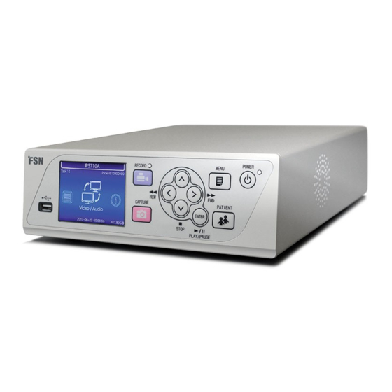
Turn Power On IPS710A Move the AC On/Off switch on the back of IPS710 to the ON position. This will automatically start the initialization process. If the back AC On/Off switch is already in the ON position, and there is no image on the front LCD... - Page 20 Internal Front User Interface IPS710A The LCD screen on the front of IPS710A is primarily used as a live preview for the active input video source. The LCD can also be used as a secondary method to adjust some user interface op- tions for File List, Audio/Video, Information, and Setup.
- Page 21 External Monitor User Interface IPS710A When an external monitor is connected to IPS710A, a built-in interface will show on the moni- tor after IPS710A has initialized. This interface can be controlled with a mouse and keyboard attached to IPS710A, or by using a touchscreen external monitor.
- Page 22 Task A task in IPS710A is a group of captured or recorded images that have been created in the same session or procedure. Patient and doctor information is associated with content in a task. After a task has been closed, additional content can no longer be added to the task. A task number is automatically given by IPS710A to each new task.
- Page 23 Use the Setup dashboard to confi gure the system and any connected devices. Setup also defi nes what type of fi les will be captured or recorded. Each IPS710A installation has unique requirements for communicating with other information systems. Specialized modifi cations are required by, and should be set-up by, each facility’s IT department in order to integrate protocols such as FTP/Samba, DICOM, network addresses, etc.
- Page 24 External Monitor User Interface - Record IPS710A Record Press the button to open the dashboard where capture and recording are initiated. A new task must fi rst be created before any recording can take place. When creating a task, specifi c...
- Page 25 External Monitor User Interface - Task List IPS710A Task List Press the button to open the dashboard where all tasks and fi le thumbnails can be viewed . All tasks stored on the internal hard disk drive are listed here.
- Page 26 General Specifi cation IPS710A Item Description Still image capture Up to 1920 x 1080p Video recording Up to 1920 x 1080p Standalone preview Front 3.5 inch TFT LCD screen Front LCD screen or graphic user Main Functions Menu access interface running on a monitor/mouse/...
-
Page 27: Dimensions
General Specifi cation IPS710A Item Description Spanish, Italian, French, German, Polish, Multi-language UI Portuguese, Chinese, Korean, Japanese, English Power Requirements AC 100-240V / 50-60Hz , 0.6A(max) Power Consumption 32.5W max Dimensions 250mm x 87mm x 300mm (W x H x D) - Page 28 Input/Output Timing IPS710A DVI input Horizontal Resolution Vertical Frequency (Hz) Clock Frequency (MHz) Frequency (KHz) 720 X 400 @70Hz 31.50 70.00 28.32 640 X 480 @60Hz 31.50 60.00 25.17 640 X 480 @75Hz 37.50 75.00 31.50 800 X 600 @60Hz 37.90...
- Page 29 Dimensions IPS710A 10/2021...
-
Page 30: Ips740Ds, Ips740Dg
Accessories IPS740 series Packaging cushion IPS740DS or AC power cord IPS740DG unit (6ft, 1.8 m medical grade) User’s guide Shipping box HDMI cable (2 m) DisplayPort cable (6ft, 1.8 m) IPS740DS IPS740DG 1 SDI cable 4 SDI cables (6ft, 1.8 m) (6ft, 1.8 m) 10/2021... - Page 31 Front Panel IPS740 series POWER on/off button. LED indicator when the back Select the MONITOR icon to With the back panel panel power switch in the ON switch to the connected ex- power switch in the ON position: ternal monitor. When in this position, press to start Green = standby mode, touchscreen can also...
- Page 32 Back Panel IPS740 series IPS740DS 10 11 IPS740DG AC ON/OFF Switch (ON: Green LED) DISPLAYPORT1.2 Input Earth Terminal HDMI Input (up to 4096x2160p@60) AC Inlet HDMI Output (1920x1080p@60/3840x2160p@60) DC Inlet (For use as an auxiliary power PEDAL Input (Capture, 3.5mm) supply to prevent fi le errors during recording when a power failure occurs.) 3G-SDI4 Input (BNC-75Ω)
- Page 33 User Interface - Front Panel Only IPS740 series Connect to back Active signal is previewed on the front panel of recorder. Video source. LCD. Tap the LCD to show icons for: • Home • File • Worklist • Setup • Monitor (if connected) •...
-
Page 34: User Interface
Turn Power On IPS740 series Move the AC On/Off switch on the back panel to the ON position. Press the power button on the front panel to start the initialization process. Turn Power Off Press the power button on the front panel and follow the directions on the user interface. - Page 35 Date, Time, Data Storage Capacity IPS740 series Front Panel LCD 2:3.06 GB H:3.39 TB 2019-10-23 08:58 USB memory stick Internal hard disk drive Current date and time. remaining capacity. remaining capacity. External Monitor 10/2021...
- Page 36 Tasks IPS740 series A task in IPS740DS or IPS740DG is a collection of captured or recorded images that have been created during the same session or procedure. Patient information is associated with content in a task. After a task has been closed, additional content can no longer be added to the task. Task information can be modifi ed after a task has been closed.
- Page 37 Open Existing Task IPS740 series Select the FILE icon to manage tasks, including: search, modify, copy, delete, DICOM store, and print. After a task has been closed, additional content can no longer be added to the task. External Monitor Front Panel LCD Close Task IPS740 series External Monitor Front Panel LCD...
- Page 38 Capturing Still Images IPS740 series Connect an input source signal. Make sure a task has been created and the input source signal is being shown in the preview window of the front panel LCD or the external monitor. External Monitor Front Panel LCD Select the camera icon to capture an image.
- Page 39 Task Actions IPS740 series Select the FILE icon to manage tasks, including: search, modify, copy, delete, DICOM store, and print. After a task has been closed, additional content can no longer be added to the task. From the list of stored tasks, select a task by clicking the box to the left of the Patient ID column.
- Page 40 File Actions IPS740 series Double-click a task and all the fi les contained in the task are displayed in the left window. External Monitor Front Panel LCD Selects all fi les in Sorts all fi les in Sorts all fi les in the the task.
- Page 41 File Playback IPS740 series Double-click a task and all the fi les contained in the task are displayed in the left window. Next double-click an image fi le, it will be opened full-screen. Video fi les are marked with a fi lm symbol, and are opened with the play icon. Click play to start, as the video is played back, the progress bar increases.
- Page 42 Creating Tasks Using Worklist Information IPS740 series Before retrieving worklist information, worklist server settings should be properly confi gured in the Setup -> System menu. Select the WORKLIST icon. Patient information that is stored on the worklist server will be presented in the left window.
- Page 43 Setup IPS740 series Select the SETUP icon, wrench image on LCD or gear image on external monitor, to manage system settings as outlined below. If password protection has been enabled, the password authentication dialog will be opened. External Monitor Front Panel LCD Setup Menu Sub Menu Item Setup Descriptions...
-
Page 44: General Specifi Cation
General Specifi cation IPS740 series Item Description Video recording Up to 3840 x 2160p 60Hz Still image capture Up to 3840 x 2160 Standalone preview Front LCD screen Main Menu access Front LCD touchscreen, or GUI on HDMI monitor output Functions DICOM store (image &... - Page 45 Input/Output Timing IPS740 series HDMI input Resolution Horizontal Frequency (KHz) Vertical Frequency (Hz) Clock Frequency (MHz) 640 x 480 31.47 59.94 25.173 800 x 600 37.88 60.32 40.00 1024 x 768 48.36 60.00 65.00 1280 x 720 44.76 60.00 74.486 1280 x 1024 63.98 60.02...
- Page 46 Dimensions IPS740 series 10/2021...
- Page 47 Cleaning Instructions Follow your hospital protocol for the handling of blood and body fl uids. Clean the device with a diluted mixture of mild detergent and water. Use a soft cotton towel or swab. Use of certain detergents may cause degradation to the labels and plastic components of the product. Consult cleanser manufacturer to see if agent is compatible.
- Page 48 Thank you for choosing our product. Service Contact the appropriate customer service listed below for product information or assistance. Warranty One year, parts and labor. EC Representative KTR Europe GmbH Mergenthalerallee 77, Eschborn 65760, Germany Tel : +49(0)6196-887170 FORESEESON GmbH Industriestrasse 38a, 63150 Heusenstamm, Germany Tel.
Need help?
Do you have a question about the IPS710A and is the answer not in the manual?
Questions and answers