Table of Contents
Advertisement
Quick Links
Advertisement
Table of Contents

Related Manuals for Suntex TC-7310-RS-M


Summary of Contents for Suntex TC-7310-RS-M
- Page 1 TC-7310-RS-M Operation Intelligent Manual MLSS Transmitter...
-
Page 2: Precautions For Installation
When using this transmitter, please follow all instructions on installation and operation as described within this manual. Suntex Instruments Co., Ltd. is not liable for any direct or indirect loss or damages caused by improper usage of this product. If there are any omissions or mistakes, questions or concerns, regarding the product of this operation manual, please contact our staff. -
Page 3: Table Of Contents
Specifications Assembly and Installation 2.1 Transmitter Installation 2.2 Panel Mounting Illustration 2.3 Wall Mounting and Pipe Mounting Illustration Overview of MLSS Transmitter TC-7310-RS-M 3.1 Rear Panel Illustration 3.2 Terminal Function Illustration 3.3 Terminal Function Description 3.4 Cable Wiring 3.5 Electrical Connection Illustration Configuration 4.1 Front Panel Illustration... - Page 4 7.6 Relay 1 7.7 Relay 2 7.8 Wiper 7.9 Electrode Zero 7.10 Clean 7.11 Analog Output 7.12 Date/Time (Clock) 7.13 RS-485 Communication 7.14 Sample Measurement Average (Digital Filter) 7.15 Backlight 7.16 Contrast 7.17 Logbook 7.18 Automatic Return (Return) 8. Calibration Calibration Block Diagram 8.1 Calibration Setup Menu 8.2 Calibration Security Code (Code)
-
Page 5: Brief Instructions
Brief Instructions Description of Setup Settings (See Chapter 7 for Details) Press simultaneously to see the overview of the setup settings. Then press modify setup settings. Press keypad according to the index bar on the bottom of the screen. Index of Keypad Keypad Index Bar Description... -
Page 6: Relay
Relay 2 Second relay settings, select action off or Hi/Lo alarm Automatic wiper wash time settings, adjust detector window Wiper cleaning duration and interval Electrode Sensor itself zero point correction, for sensor internal Zero calibration Automatic wash time settings; adjust external sensor cleaning Clean device ON and OFF duration Analog... - Page 7 Description of Calibration Settings (See Chapter 8 for Details) Press simultaneously to see the last calibration information. Press to make a new calibration or to modify calibration settings. Press keypad according to the index bar on the bottom of the screen. Index of Keypad: Keypad Index Bar...
-
Page 8: Specifications
1. Specifications Model TC-7310-RS-M Measuring Mode MLSS Measuring Unit mg/l, ppm 0~50,000 mg/l (ppm) Measuring Range (TS-MxS-A sensor) Resolution 1 mg/l (ppm) Selection by MLSS, Defined, Digested Sludge and Activated Sludge. Except MLSS, other 3 matrix types provide display value alarm... -
Page 9: Assembly And Installation
2. Assembly and Installation 2.1 Transmitter Installation The transmitter can be installed by panel mounting, wall mounting, or 2” pipe mounting. Panel Mounting: Prepare a square hole of 138 mm x 138 mm on the panel box, and then insert the controller directly into the hole. -
Page 10: Wall Mounting And Pipe Mounting Illustration
2.3 Wall Mounting and Pipe Mounting Illustration Sun Shield (wall mounting, optional) Sun Shield (pipe mounting, optional) (Order No.: 8-35 + 8-35-2) (Order No.: 8-35 + 8-35-1) Insert rubber plug into Pipe mounting illustration, unused cable glands. fix with a U-shaped pipe Tighten up the cable gland clamp (optional). -
Page 11: Overview Of Mlss Transmitter Tc-7310-Rs-M
3. Overview of MLSS Transmitter TC-7310-RS-M 3.1 Rear Panel Illustration: 3.2 Terminal Function Illustration: POWER RS-485 D+(B) Cal. D-(A) INPUT + POWER - 4/20m Check REL1 REL2 WASH/Cln Shield... -
Page 12: Terminal Function Description
3.3 Terminal Function Description 1 100~240 AC: Power supply terminal 2 3 WASH: Wash relay contact for an external relay 4 5 REL2: Second alarm control, the contact for an external relay 6 7 REL1: First alarm control, the contact for an external relay 8... -
Page 13: Electrical Connection Illustration
3.5 Electrical Connection Illustration 100V~240VAC Transmitter Relay 1 Relay 2 WASH/Cln 100V~240VAC Surge absorber Surge absorber External relay Cleaning device Surge absorber Surge absorber External relay Dose feeder Surge absorber Surge absorber External relay Dose feeder Note: The transmitter’s built-in miniature relays are required to be repaired and replaced by professional technicians. -
Page 14: Configuration
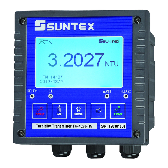
4. Configuration 4.1 Front Panel Illustration: 4.2 Keypad: In order to prevent unauthorized operations, he transmitter utilizes multi-key and passcode functions to enter parameter and calibration setting modes. Descriptions of the key functions are as follows: : In parameter set-up mode, press this key to exit and return to measurement mode. :... -
Page 15: Operation
5. Operation 5.1 Measurement Mode: After all electrical connections are secured and tested, connect the instrument to the power supply and turn it on. The transmitter will automatically enter measurement mode with the factory default settings or the previous user settings. 5.2 Setup Menu: Please refer to the set-up instructions in Chapter 7. -
Page 16: Calibration Default Values
5.5.2 Calibration Default Values: Calibration unit: mg/l Calibration point: No Cal. Correction factor: 1.0000 Auto return: Auto, 3 minutes Code settings: OFF Note: The factory default calibration setting is “No Cal”, and the calibration value is “None”. This means that the user has not yet calibrated the sensor with the transmitter. After every calibration, the calibration information display will be updated. -
Page 17: Measurement Display Mode
6. Measurement Display Mode 6.1 Text Mode Text mode is the main measurement screen and shows the measurement value and unit, temperature compensation mode, temperature measurement and unit, time and date, as seen in the following illustration. Main measurement Matrix table type Main measurement unit Time and date... -
Page 18: Real-Time Chart Mode
6.2 Real-Time Chart mode Real-time chart mode shows a dynamic change of the measuring values during the last 3 minutes. Under setting mode, users are allowed to set corresponding MLSS measuring range (see section 7.4) to adjust the resolution of the curve. The smaller the range is being set, the higher resolution the display is. -
Page 19: Trace Mode
6.3 Trace mode Trace mode features value tracing on a graph with duration configurable from three minutes up to four weeks. The graph is composed of 60 record sets over time interval T. Each set of data (T/60) is displayed by calculating the mean, maximum, and minimum value of the previous 60 values. -
Page 20: Warning Symbols And Text
6.4 Warning Symbols and Text 1. When detector wiper is activated, the display will show “HOLD” and flash “Wiper Running”. At the same time, the transmitter will automatically turn off Relay 1 and Relay 2 function. After wiper cleaning is completed, both Relay 1 and Relay 2 will automatically returns normal status. 2. -
Page 21: Settings Block Diagram
7. Settings Settings Block Diagram – Part 1... - Page 22 Settings Block Diagram – Part 2...
-
Page 23: Setup Menu
7.1 Setup Menu Under measurement mode, press the two keys simultaneously to enter the current settings overview. Press to enter setup mode to modify the settings if necessary. “Measurement (Mode)” Press Press Press Press Press to confirm it Setup Menu... -
Page 24: Settings Security Code (Code)
7.2 Settings Security Code (Code) After entering setup mode, select “Code” and press to enter code setting procedure. The preset settings code is 1111. Note: The code for settings mode is at a higher security level than the code for calibration. Thus, the code for setting mode can be used to unlock calibration mode. -
Page 25: Language
7.3 Language After entering setup mode, select “Language” and press to enter system language selection. Select from English, Traditional Chinese or Simplified Chinese. Press to confirm it. Press Press to switch to switch Press to confirm it. Enter “Mode/Unit” Setup... -
Page 26: Measurement Parameter (Mode)
7.4 Measurement Mode/Unit (Mode/Unit) After entering setup mode, select “Mode/Unit” and press to configure measurement settings: reference table, unit, and display mode. Selectable mode include: MLSS, Digested Sludge, Activated Sludge, and Defined. • MLSS: (mg/l or ppm) • Activated Sludge Matrix: Built-in activated TSS and SiO matrix curve (mg/l). - Page 27 Measurement Display Settings Press Press select display mode. select display mode. Press to confirm it. Select NO to keep previously recorded data. Press confirm it. Press adjust maximum value. Select YES and press Press to confirm it. Press to confirm it. Press Press to confirm it.
- Page 28 User Defined Table (Defined) This transmitter features a user definable reference table to create an application suitable calibration curve. User defined table requires at least two reference points and allows at most 10 reference points. The more reference points provided, the higher the conversion accuracy. MLSS measurement unit and transferred (Trans.) unit can be set as mg/l or ppm.
-
Page 29: Product Adjustment
7.5 Product Adjustment After entering setup mode, select “Code” and press to make fine adjustments to the measurement reading. Users are able to make sample reading adjustments based on actual sample measurement values without retrieving the sensor for calibration. A PDT icon will display on the main screen above the measurement unit if the product is adjusted (see section 6.4). - Page 30 7.6 Relay 1 Enter setup of Relay 1. Select the item to turn the relay 1 function ON / OFF. If you select to turn on relay 1, set relay 1 as “High set-point” alarm or “Low set-point” alarm. Set the value of set-point (SP) and Hysteresis (Hys.).
- Page 31 7.7 Relay 2 Enter setup of Relay 2. Select whether to turn on or turn off the relay 2 function. If you select to turn on the relay 2, then select for using relay 2 as “High set-point” alarm or “Low set-point”...
-
Page 32: Wiper
7.8 Wiper After entering setup mode, select “Wiper” and press to configure wiper settings: activation mode and time interval. Select Auto to set automatic wiper cleaning every 10 minutes. Select Manual to configure automatic cleaning interval between 2 to 9 minutes. Adjust cleaning frequency as needed to suit application requirement. -
Page 33: Electrode Zero
7.9 Electrode Zero After entering setup mode, select “Electrode Zero” and press to perform zero-point calibration. The user can determine if zero-point calibration is necessary from deviation of the electrode’s measurement values. If calibration procedure is necessary, the electrode must be placed into distilled or deionized water for zero-point calibration. -
Page 34: Clean
7.10 Clean Enter setup of “Clean” function. Select the icon to turn on or turn off the clean function. Select “Auto” to turn on the function as automatic. Set the timer for the clean function to automatically turn cleaning on or off, and then set the Hysteresis value (Hys.). Note: When the clean function is turned on, if any value is set to 0, the instrument will automatically turn off this function. -
Page 35: Analog Output
7.11 Analog Output Enter setup of Analog. Select 0~20 mA or 4~20 mA current output. Set the related value to the range of MLSS measurement. The smaller the range of the MLSS measurement is set, the higher the resolution of current output. When the measured value exceeds the higher range limit, the current will remain approximately 22 mA output. -
Page 36: Date/Time (Clock)
7.12 Date/Time (Clock) Enter setup of Date/Time (Clock). Set the “Year”, “Month”, “Date”, “Hour”, and “Minute”. If you select to turn off the clock function, a clock will not be displayed under measurement mode. The calibration time of calibration records will also show “OFF” under calibration overview display. -
Page 37: Rs-485 Communication
7.13 RS-485 Communication Enter setup of RS-485 communications. According to the Modbus protocol, set the transmitting mode, parity, baud rate, stop bit, and ID number. About the details of Modbus protocol, please refer to chapter 9. If under hold status, the measurement signal output maintains the last output value before hold status. -
Page 38: Sample Measurement Average (Digital Filter)
7.14 Sample Measurement Average (Digital Filter) Enter setup of “Digital Filter”. You may select the number of sample measurements to be averaged for each reading to increase the stability of the displayed measurement. The greater the number, the more stable the measurement value; the smaller the number, the more acute the measurement value. -
Page 39: Backlight
7.15 Backlight Enter setup of backlight display. According to your needs, you can set the brightness of the display (-2~2, dark ~ bright) and sensitivity of the brightness sensor (-2~2, insensitive ~ sensitive). Whether under OFF or AUTO mode, the touch-on function will activate the backlight when any button is pressed. -
Page 40: Contrast
7.16 Contrast Enter setup of display contrast. You can set the contrast of display according to your needs (-2, -1, 0, 1, 2, light to dark). Press to confirm it. Press to select display contrast level. Press to confirm it. Enter “Logbook”... -
Page 41: Logbook
7.17 Logbook Enter setup of Logbook. It is available for user to look up 50 sets of important events and error diagnosis records. The user can read important events by either by Logbook or Modbus. For detailed definitions of events please see to section 9.2, Modbus Address and Command Table. Press to confirm it. -
Page 42: Automatic Return (Return)
7.18 Automatic Return (Return) Enter setup of auto return mode “Return” to set the instrument to automatically exit the setup menu after a period of time without pressing any keys. The “Manual Exit” means that it needs to exit setup menu manually, while “Auto” means that the display automatically exits the setup menu and returns to measurement mode after a period of time without pressing any keys. -
Page 43: Calibration
8. Calibration TC-7310-RS-M Calibration Block Diagram Calibration Information Correction Return Code Known Sol. Factor MLSS Activated Sludge Input Select Cal. Factor Digested Sludge Auto Manual Passcode Unit Adjustment Defined Return Exit Select First Input Buffer Range Return Time Adjust First Cal. -
Page 44: Calibration Setup Menu
8.1 Calibration Setup Menu Under measurement mode, press simultaneously to display Calibration Information. If you do not need to re-calibrate the measurement system, press to return to measurement mode. If you need to re-calibrate the system, press to enter calibration setup menu. -
Page 45: Calibration Security Code (Code)
8.2 Calibration Security Code (Code) Select the “Code” (passcode) after entering calibration setup mode. Select to activate passcode function. The preset calibration settings code is 1100. Press to confirm it. The first “0” of digits “0000” will start to flash. Press to adjust the value, then press When an incorrect code is to confirm it and proceed to the... -
Page 46: Calibration
8.3 Calibration As each sensor has its unique characteristics, the transmitter is not calibrated to a sensor by default (Cal. Point: No Cal). Calibration procedure must be performed by trained personnel each time a new sensor is connected. This instrument provides multi-point standard buffer solution calibration allowing users to decide the number of points to calibrate against. - Page 47 Press to complete two-point calibration and directly display the The sensor will display result. the current received. Press to continue Wait until the value is and proceed to multi- stable. point calibration Press to confirm it. Press to directly display the result or wait for the transmitter to Calibration results automatically confirm it.
-
Page 48: Correction Factor
8.3.1.2 Activated Sludge and Digested Sludge Calibration Matrix Calibration procedure is identical to MLSS calibration procedure (see section 8.3.1.1, MLSS Calibration). Unit selection is not applicable. Calibration unit is set at mg/l. 5 preset standard solution values are available for selection: 40000, 20000, 10000, 5000, 500.0. -
Page 49: Automatic Return (Return)
8.5 Automatic Return (Return) Enter setup of auto return mode (Return) to set the function that the instrument automatically exit the setup menu after a period of time without pressing any key. The “Manual Exit” requires the user to exit calibration menu manually; “Auto” sets the display to automatically exit calibration mode and return to measurement mode after a set time of user inactivity. -
Page 50: Modbus Protocol And Instructions
D+(B) Terminator ︴ GND Master D-(A) Pull-low ︴ resistor pull- Other TC-7310-RS-M TC-7310-RS-M ..Modbus ID: 02 ID: 01 Depends on site equipment conditions Note: 1. The transmitter’s RS-485 interface is equipped with a protective ground terminal. When communicating with the RS-485, the ground terminal must be used to eliminate safety risks. - Page 51 therefore users will need to be more aware of the settings. Some equipment parts (RS-485 converters or modules) provide terminating, pull-high, pull-low resistors, and VBus settings. Please refer to the corresponding operation manuals before installation and connection. For VBus, the standard is 5 V, for pull-high and pull-low resistors, 1 K, and for terminating resistors, 120 K.
-
Page 52: Modbus Name And Address Table
9.2 MODBUS Name and Address Table Modbus response table is as follows. As users communicate with transmitters through PLC or Man- machine Interface, check to see if the transmission of address subtracts 1 by default. If so, add 1 onto each address to match the table;... - Page 53 0: OFF 0015H USHORT 1: AUTO 0: AUTO 0016H USHORT 1: Lo Relay 1 * Data 0017H FLOAT 40000 mg/l affected by sign 0019H FLOAT Hys1 10 mg/l byte 0: OFF 001BH USHORT 1: AUTO 0: Hi 001CH USHORT 1: Lo Relay 2 * 10000 Data...
- Page 54 002AH USHORT Minute 2016-01-01 00:00:00 002BH USHORT Hour 002CH USHORT 002DH USHORT Month 002EH USHORT Year 002FH Event ID USHORT 0~12 Wiper Act. 0030H USHORT Minute Time Interval Note 1: Actions without * only supports function code 03H. Actions with * supports function code 03H, 06H, 10H.
- Page 55 Function Code: 03H Modbus response (measurement parameter) Logic Information Description of data Default Number Item Note of Byte address type transmission value 0: Hold status Measurement 0031H USHORT status 1: Measurement status ASCII 0032H Sign byte CHAR mg/l code mg/l MLSS MLSS 0035H...
-
Page 56: Modbus Example Description
9.3 Modbus Description Example (e.g.: function code 03H) The following description uses MLSS reading 0035H as an example. If the MLSS is 25 mg/l, confirm that the host and sub-machine communication format settings are correct. The host sends request commands according to the left column of the table below, then receives a corresponding response from the sub-machine according to the right column. -
Page 57: Error Messages (Error Code)
10. Error Messages (Error Code) Messages Reason Dispositions Please check if the standard Slope exceeds the upper or Error2 solution has been re-used during lower limit the calibration or is expired. Please check and clear electrode The readout is unstable glass bubbles, Error3... -
Page 58: Appendix
Appendix Table 1: Activated Sludge (TSS-SiO [mg/l] 1370 2600 3220 3910 Total suspended solids [mg/l] 2400 3390 4420 (Activated sludge value) [mg/l] 4860 5850 6520 7050 7160 Total suspended solids [mg/l] 6210 8800 11620 15550 17570 (Activated sludge value) Table 2: Digested Sludge (TSS-SiO [mg/l] 1130 1730... - Page 59 ...
- Page 60 SUNTEX INSTRUMENTS CO., LTD. 13F, No. 31, Lane 169, Kangning St., Xizhi Dist., New Taipei City, Taiwan (R.O.C.) Tel: 886-2-2695-9688 Fax: 886-2-2695-9693 www.suntex.com.tw/en e-mail: suntex@ms1.hinet.net 5040E TC-7310-RS-M/Technical data subject to alternations/ Quality Systems ISO 9001/201711...
Need help?
Do you have a question about the TC-7310-RS-M and is the answer not in the manual?
Questions and answers