Table of Contents
Advertisement
Quick Links
Advertisement
Table of Contents

Related Manuals for Suntex PC-3110-P


Summary of Contents for Suntex PC-3110-P
- Page 1 PC-3110-P Operation Intelligent Manual pH/ORP Transmitter...
-
Page 2: Table Of Contents
2.4 Assembly of electrode and housing 2.4.1 Cable set-up 2.4.2 Assembly of housing PP-100A 2.5 Illustration and description of junction box Overview of Intelligent pH/ORP transmitter PC-3110-P 3.1 Illustration of rear panel 3.2 Illustration of terminal function 3.3 Description of terminal function 3.4 Installation of transmitter PH-300T... - Page 3 6.3 Language 6.4 Measurement parameters(Mode) 6.5 Multi-point calibration(Multi-Cal) 6.6 Temperature 6.7 PID control 6.8 Relay 1 6.9 Relay 2 6.10 Wash time(Clean) 6.11 Analog output 1 (pH/ORP) 6.12 Analog output 2 (temperature/PID) 6.13 Date/Time (Clock) 6.14 Sample average of measurements (Digital filter) 6.15 Backlight settings 6.16 Contrast settings 6.17 Automatically back to measurement mode(Return)
-
Page 4: Precautions For Installation
Precautions for installation Wrong wiring will lead to breakdown or electrical shock of the instrument, please read this operation manual clearly before installation. Make sure to remove AC power from the controller before wiring input, output connections, and remove it before opening the controller housing. The installation site of the controller should be good in ventilation and avoid direct sunshine. -
Page 5: Brief Instruction
Brief Instruction Description of set-up settings (see chapter 7 for details) Press simultaneously to see the overview of the set-up settings now. Then press if you would like to modify set-up settings. Press keypad according to index of keypad on the screen. Index of keypad keypad Accordingly item... -
Page 6: Relay
Current output according to pH or ORP setting range Analog 1 Current output according to temperature/PID setting range Analog 2 Clock setting (When out of power and reboot it, the Clock instrument’s time setting will return to the factory default setting) Backlight setting, to set Auto/ON/OFF backlight, brightness, Black-light... - Page 7 Description of calibration settings (see chapter 8 for details) Press simultaneously to see the last calibration information. Then press if you would like to make a new calibration or modify setting of calibration. Press keypad according to index of keypad on the screen. Index of keypad: keypad Accordingly item...
-
Page 8: Specifications
1. Specifications Model PC-3110-P Measuring modes pH / ORP / Temp. -2.00~16.00 pH -1999~1999 mV Ranges -30.0~130.0 C Temp. 0.01 pH Resolutions 1 mV 0.1 C Temp. ±0.01 pH ± 1 Digit Accuracy ±0.1% ± 1 Digit Temp. ±0.2C± 1 Digit... -
Page 9: Assembly And Installation
2. Assembly and installation 2.1 Transmitter installation: This Transmitter can be installed through panel mounting, wall mounting and pipe mounting. Installation of panel mounting: First, prepare a square hole of 93 x 93mm on the panel box, and then insert the controller directly into the panel box. Insert the accessorial mounting bracket from the rear, and make it be fixed in to pickup groove. -
Page 10: Illustration Of Wall Mounting And Pipe Mounting
2.3 Illustration of Wall mounting and pipe mounting Installation of pipe mounting Installation of wall mounting Fixed with U-shaped pipe clip. The Fixed with 4 x M4 screws distance between screw holes is 60mm Sun Shield (Pipe mounting) Sun Shield (Wall mounting) Order No.: 8-35 and 8-35-1 Order No.: 8-35 and 8-35-2 2.4 Assembly of electrode and housing... -
Page 11: Assembly Of Housing Pp-100A
2.4.2 Assembly of housing PP-100A A------ Upper cover of round joint box B------ O-ring C------ Cable fixing point MG16A D------ Lower cover of round joint box E------ Cable fixing point MG16A F------ O-ring G------ PP Electrode Protective Housing H------ Electrode (Sensor) I------- Rubber electrode holder J------- PP pipe protective cover 1. -
Page 12: Illustration And Description Of Junction Box
Our company use L-shaped mounting bracket as electrode mounting bracket. According to the site necessity, fix the bracket with steel nails or expansion bolts at proper locations by pool. 2.5 Illustration and description of junction box :( Two kinds of link distributing system) [1]Two-wire distributing system INPUT terminals Terminal... - Page 13 1.) If temperature probe is not used, the Order No. is 7202-RG-58. 2.) If temperature probe is used, the Order No. is 7202-F94009-BK. 2. If temperatures probe 8-26-3(NTC30K) or 8-26-8(PT1000) is used for two-wire distribution, the black wire terminal should be forbidden. 〔2〕Three-wire distributing system IN terminals Terminal...
-
Page 14: Illustration Of Rear Panel
3. Overview of pH transmitter PC-3110-P 3.1 Illustration of rear panel: 3.2 Illustration of terminal function: POWER GLASS 4/20m INPUT POWER 4/20m WASH ±12V... -
Page 15: Description Of Terminal Function
3.3 Description of terminal function: 01 REL1: First external relay terminal control; 02 or PID Direct control 03 REL2: Second external relay terminal control; 04 or PID Reverse control 05 WASH: External wash relay terminal 06 07 NC: None contact 08... -
Page 16: Installation Of Transmitter Ph-300T
3.4 Installation of transmitter PH-300T: (alternative equipment) PH-300T transmitter is mainly installed on the electrode protective pipe, but also can apply wall mounting and pipe mounting. For long distance transmission (100m), if PC-3110 is more than 30m far away from the electrode, PH-300T transmitter is recommended to avoid the attenuation of electrode signal, and for the convenience of onsite observation, measurement, and calibration. -
Page 17: Typical Wirings
3.6 Typical wirings: Two-wire distribution Three-wire distribution GLAS REF. REF. GLAS Coaxial Coaxial Coaxial Coaxial shield Black shield inner inner Short circuit slice... -
Page 18: Illustration Of Electrical Connection
3.7 Illustration of electrical connection: 100 ~ 240VAC Transmitter Surge absorber Surge absorber External relay Washing device Surge absorber Surge absorber External relay Dose feeder Surge absorber Surge absorber External relay Dose feeder... -
Page 19: Configuration
4. Configuration: 4.1 Illustration of front panel: 4.2 Keypad: In order to prevent inappropriate operation by others, before the parameter setting and calibration, the operation applies multi-keys, and coding protection if necessary. Description of the key functions is in the following: :In the parameter set-up mode, pressing this key allows you exit parameter set-up mode and back to Measurement mode. -
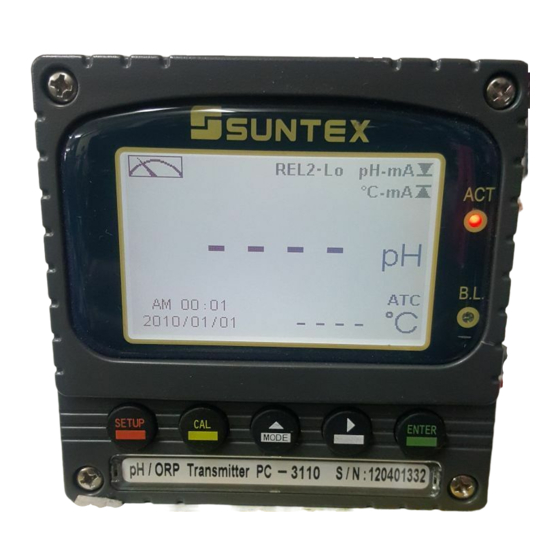
Page 20: Display
4.4 Display: Analog 1 output REL 1 high or REL 2 high or current over range low point alarm low point alarm Measurement mode alarm Analog 2 output current over range Set-up mode alarm Calibration mode Control function on hold Measurement value Measurement unit Temperature... -
Page 21: Operation
5. Operation 5.1 Measurement mode: After all electrical connections are finished and tested, connect the instrument to the power supply and turn it on. The transmitter will automatically entering measurement mode with the factory default settings or the last settings from user. 5.2 Set-up menu: Please refer to the set-up instructions in Chapter 6. -
Page 22: Settings
6. Settings Block diagram of settings 1 Overview Configure mode Return Code Mode Multi-Cal. Temperature Relay1 Relay2 Clean Language Setting Setting Setting Setting Setting Setting Setting Setting Setting Setting Activate Relay1 Relay2 Traditio Simpli- Input pH/ORP Points Select temp. On/Off On/Off English -nal... - Page 23 Block diagram of settings 2 Digital Code Relay2 Clean pH/ORP Temp Clock Backlight Contrast Return Filter Setting Setting Setting Analog 1 Analog 2 Setting Setting Setting Setting Setting 0/20 or 0/20 or Signal Clean Contrast 4/20mA 4/20mA Set year average Active time input Select...
-
Page 24: Entry Of Set-Up Menu
6.1 Entry of set-up menu In the measurement mode, pressing the two keys simultaneously allows you enter the overview of current setting, and press to enter the set-up mode to modify the setting if necessary. “Measurement (Mode)” Press Press Press Press to confirm it Enter set-up menu... -
Page 25: Security Code Of Settings(Code)
6.2 Security code of settings After entering set-up mode, select “code” item, press to enter into code procedure. The code pre-setting is 1111. Note: The code of setting mode is prior to the code for calibration. That means that the code of setting mode can be used for the code of calibration mode. Press to confirm it. -
Page 26: Language
6.3 Language Enter Language setup menu, select the system language from English, Traditional Chinese and Simplified Chinese. Press to confirm it. Press Press to select to select language type language type Press to confirm it. Enter “Measurement Mode” Setup... -
Page 27: Measurement Parameters(Mode)
6.4 Mode Enter setup of “Mode”. Select between “pH” or “ORP” measurement. Press to confirm it. Press to select between pH or ORP Press to confirm it. Enter ”Multi-Cal” Setup... -
Page 28: Multi-Point Calibration(Multi-Cal)
6.5 Multi-Cal Enter setup of multi-points calibration to set the number of calibration points. Press to confirm it. Press to select the number of calibration points. There are 1~3 points to choose from. The factory default is 2 points. When the calibration reaches the number of setting points, the calibration procedure will automatically be terminated and display the calibration result. -
Page 29: Temperature
6.6 Temperature Enter setup of “Temperature” to select temperature compensation mode. Select from NTC(NTC 30K), PTC(PT 1K) or MTC(Manual adjustment). Press to confirm it. Press Press to select to select Press to confirm it. Press to confirm it. Use standard thermometer to test If necessary, compare with the actual temperature of the the actual temperature value... -
Page 30: Pid Control
6.7 PID Control Enter setup of PID to set PID controlling parameters. The parameters related definitions please refer to Chapter 8 of the PID control. If select to turn on PID control, the relays or analog outputs may be turned off according to PID output type. Press select whether to turn on or turn off PID control... - Page 31 6.8 Relay 1 Enter setup of Relay 1. Select the item to turn on or turn of the relay 1 function. If you select to turn on the relay 1, then select for using relay 1 as “Hi set-point” alarm or “Low set-point”...
- Page 32 6.9 Relay 2 Enter setup of Relay 2. Select the item to turn on or turn of the relay 2 function. If you select to turn on the relay 2, then select for using relay 2 as “Hi set-point” alarm or “Low set-point”...
-
Page 33: Wash Time(Clean)
6.10 Clean Enter setup of “Clean” function. Select the icon to turn on or turn off the clean function. If you select “Auto” turning on, and set the timer of the clean function including automatically turning on time and turning off time, and set the bead-band value(DB). Note: When the clean function is turned on, if any value is set to be 0, the instrument will automatically turn off this function. -
Page 34: Analog Output 1 (Ph/Orp)
6.11 Analog output 1 (pH/ORP): Enter setup of Analog 1. Select 0~20mA or 4~20mA current output. Set the related value to the range of pH/ORP measurement. If the range or the pH/ORP measurement is smaller, the resolution of current output is higher. When the measured value exceeds the higher range limit, the current will remain approximately 22mA output. -
Page 35: Analog Output 2 (Temperature/Pid)
6.12 Analog output 2 (Temperature/PID): Enter setup of Analog 2. Select 0~20mA or 4~20mA current output. Set the related value to the range of temperature measurement. If the range or the temperature measurement is smaller, the resolution of current output is higher. When the measured value exceeds the higher range limit, the current will remain approximately 22mA output. -
Page 36: Date/Time(Clock)
6.13 Date/Time(Clock) Enter setup of Date/Time(Clock). Set the “Year”, “Month”, “Date”, “Hour”, and “Minute” time. Note: The clock needs to be reset once encounters power failure. Press to confirm it. Press set the year. Press to confirm it. Press set the month part, and press to move to adjust the date part. -
Page 37: Sample Average Of Measurements (Digital Filter)
6.14 Sample average of measurements (Digital Filter) Enter the setup of Digital filter. You may select the number of sample to be averaged each time to become a reading which is gradually counted in order to increase the stability of measurement. Press to confirm it. -
Page 38: Backlight Settings
6.15 Backlight settings Enter setup of backlight display. According to your need, you can set the brightness of display(-2~2, dark~bright) and sensitivity of the sensitization sensor(-2~2, insensitive ~sensitive). Where there is a keystroke, then activate the touch-on backlight function. Regardless of what kind of backlight mode, the touch-on function will activate the backlight. -
Page 39: Contrast Settings
6.16 Contrast settings Enter setup of display contrast. You can set the contrast of display according to your need. Press to confirm it. Press to select display contrast level. Press to confirm it. Enter “Auto return mode (Return)”Setup... -
Page 40: Automatically Back To Measurement Mode(Return)
6.17 Return Enter setup of auto return mode (Return) to set the function that the instrument automatically exit the setup menu after a period of time without pressing any key. The “Manual Exit” means that it needs to exit setup menu manually, while “Auto” means that the display automatically exit the setup menu and back to measurement mode after a period of time without pressing any key. -
Page 41: Calibration
7. Calibration Block diagram of Calibration Cal. Info. Calculate zero, slop, sensitivity and determination coefficient Cal. Mode Code Return TECH NIST Asymmetry Setting Setting Manual Input Auto Temp. adust for Temp. adust for Exit Temp. adust for first Paeeword first buffer first buffer buffer uffer( MTC uffer( MTC or... -
Page 42: Entry Of Calibration Menu
7.1 Enter calibration setup menu In the measurement mode, pressing the two keys simultaneously allows you enter the Calibration Information. If you do not need to re-calibrate the measurement system, press to go back to measurement mode. If you need to re-calibrate the system, press to enter to the calibration setup menu. -
Page 43: Security Password Of Calibration
7.2 Security password of calibration (Code) Select the Code (password) icon after entering calibration setup mode. Select to activate code function or not. The default Calibration setting code is “1100”. Press to confirm it. The first ‘0” of digits ‘0000” start to twinkle. -
Page 44: Automatically Back To Measurement Mode(Return)
7.3 Return Enter setup of auto return mode (Return) to set the function that the instrument automatically exit the setup menu after a period of time without pressing any key. The “Manual Exit” means that it needs to exit calibration setup menu manually, while “Auto”... -
Page 45: Ph Calibration
7.4 pH Calibration The instrument provides multi-point standard buffer solution calibration. You may decide how many points to calibrate the measurement system(up to 3-point). The principle is according to “Method of Least Squares”. Apply linear regression to calibration the electrode’s slope and zero point (Asy, Offset or Zero point). When calibrating a electrode, you may calibrate 1 to 3 point by any sequence to provide linear regression for mV and pH multi-calibration of a electrode, and to show the electrode’s slope and zero point(Asy, offset or Zero point) at 25°C. -
Page 46: Definition Of Calibration Parameter
7.4.4 Definition of calibration parameter You can calibrate the electrode by one point or up to three points of standard solutions by any sequence. As different calibration point method is applied, the definition of the zero point and slope different. Calibration point Determination The showed calibration value Zero point (Asy, offset or Zero point)= Asy... -
Page 47: Tech, Nist Buffer Calibration
7.4.5 TECH, NIST buffer Calibration The procedure below is two points calibration of TECH buffer. (The procedure is same as NIST buffer mode.) First, enter the setup of Multi-points calibration and set the number of calibration point for 2. (See chapter 6.4 Multi-Cal) Then, go to Calibration menu and select TECH mode. -
Page 48: Any Calibration
7.4.6 Any Calibration The procedure below is two points calibration of Any mode. First, enter the setup of Multi-points calibration and set the number of calibration point for 2. (See chapter 6.4 Multi-Cal) Then, go to Calibration menu and select “Any” mode. Operate the instrument as follow procedure diagram. -
Page 49: Orp Calibration
7.5 ORP Calibration Under ORP measurement mode, enter calibration setup menu. Select Calibration icon, and adjust mV value. The adjustable range is from -300mV to 300mV. Put the ORP electrode into ORP standard solution. Press to adjust the main display value until it is equal to the desirable mV value. -
Page 50: Pid Control
8. PID Control 8.1 The fundamental principle PID control block diagram shown below. The PV value(Process Variable) of control system is obtained by a pH/ORP sensor. The gap between PV and SV(Set point) is e. Feedback it to the PID controller, and then the PID controller calculate the control output volume, u, to decide the dosing volume. - Page 51 PID parameter description and setting range: Parameter Description Range Set the proportional control. The control output u and the error e is proportional to multiples. The greater the Kp value, the faster the system 0.1~9999.9 response. However, too large Kp easily makes output shocks.
- Page 52 until SP. can use as upper limit or lower limit control of PV. Pulse Length / Set type of actuator control signal. Select from Pulse Frequency / Actuator Pulse Length, Pulse Frequency, or Analogout. Analogout (Default: Pulse Length) When selecting Pulse length, the Duty Cycle Duty 1~1800 sec set the period of time proportion for Relay...
-
Page 53: Pid Control Signal
8.3 PID control signal When using relay as PID control device, the presetting of relay 1 is Direct control, while relay 2 as Reverse control. The summary is showed as following table. When as Direct or Reverse single way control, the other relay can be used as PV upper or lower limitation control. - Page 54 Pulse Frequency control The illustration of pulse frequency control as follows. The relay makes frequency proportion ON/OFF control according to control output volume u. When ON time is fixed as 0.3 sec, the OFF time is related to the setting of maximum frequency.
-
Page 55: Error Messages (Error Code)
9. Error messages (Error code) Messages Reason Dispositions Serious error that does Please call service engineer. not permit any further Error9 measuring Wrong password input Please input the correct password. Error5 1. During calibration, 1. Please adjust the buffer the buffer solution solution temperature to the temperature exceeds appropriate temperature... -
Page 56: Maintenance
10. Maintenance Generally speaking, under normal operation, the controller produced by our company need no maintenance expect regular cleaning and calibration of the electrode to ensure accurate and stable measurement and system operation. The cleaning cycle for the electrode depends on the pollution degree of the measurement sample. -
Page 57: Appendix
Appendix Table 1 TECH Mode TECH buffers TEMP℃ Buffer 4.01 Buffer 7 Buffer 10 3.999 7.087 10.241 3.998 7.053 10.155 3.999 7.031 10.116 4.002 7.011 10.047 4.006 6.996 9.998 4.011 6.985 9.952 4.018 6.976 9.925 4.031 6.971 9.874 4.047 6.969 9.843 4.055 6.969... - Page 58 SUNTEX INSTRUMENTS CO., L TD. 13F, No. 31, Lane 169, Kangning St., Xizhi Dist., New Taipei City, Taiwan (R.O.C.) Tel: 886-2-2695-9688 Fax: 886-2-2695-9693 www.suntex.com.tw/en e-mail: suntex@ms1.hinet.net 5040C PC-3110-P/Technical data subject to alternations/ Quality Systems ISO 9001/201210...
Need help?
Do you have a question about the PC-3110-P and is the answer not in the manual?
Questions and answers