Table of Contents
Advertisement
Advertisement
Table of Contents

Related Manuals for Suntex PC-3310


Summary of Contents for Suntex PC-3310
- Page 1 PC-3310 Operation Intelligent Manual pH/ORP Transmitter...
-
Page 2: Table Of Contents
3.2 Illustration of terminal function:....................10 3.3 Description of terminal function....................11 3.4 Installation of accessorial transmitter PH-300T (Optional)............12 3.5 Connection of transmitter PC-3310 and accessorial transmitter PH-300T........ 13 3.6 Typical wirings........................... 14 3.7 Illustration of electrical connection ................... 15 3.8 Online pH/ORP measurement system Optional .............. - Page 3 6.4 Mode ............................26 6.5 Multi-Cal............................ 27 6.6 Temperature ..........................28 6.7 Relay 1 ............................29 6.8 Relay 2 ............................30 6.9 Clean ............................31 6.10 Analog output 1 (pH/ORP) ...................... 32 6.11 Analog output 2 (Temperature) ....................33 6.13 Sample average of measurements (Digital Filter) ..............35 6.14 Backlight settings........................
- Page 4 The operation manual is only provided for function and installation description, Suntex Instruments Co., Ltd. is not liable for any person or entity for any direct or indirect loss or damage due to improper usage of this product. If you have any questions or find omission, negligence or mistakes of the operation manual, please contact with our staff, thank you.
-
Page 5: Brief Instruction
Mode Measurement mode, to choose pH or ORP measurement Multi-point calibration, to choose 1, 2, or 3 points Multi-Cal. calibration (PC-3310 provides up to three points calibration) Temperature measurement and compensation, including MTC, PTC, NTC (3 types total). MTC---Manual Temperature... - Page 6 Automatic wash time setting, to choose electrode clean Clean equipment’s ON and OFF duration Analog 1 Current output according to pH or ORP setting range Analog 2 Current output according to temperature setting range Clock setting (When out of power and reboot it, the Clock instrument’s time setting will return to the factory pre-setting)
- Page 7 Description of calibration settings see chapter 7 for details Press simultaneously to see the last calibration information. Then press if you would like to make a new calibration or modify setting of calibration. Press keypad according to index of keypad on the screen. Index of keypad keypad Accordingly item...
-
Page 8: Specification
1.Specification Model PC-3310 Measurement modes pH/ORP/Temp -2.00~16.00pH Ranges -1999~1999mV -30.0~130.0 TEMP 0.01pH Resolutions TEMP ±0.01pH (±1 Digit) ±0.1% (±1 Digit) Accuracy ±0.2 (±1 Digit) TEMP Equipped with temperature error modification function NTC30K / PT1K auto temperature compensation Temperature Compensation Manual adjustment temperature compensation... -
Page 9: Assembly And Installation
2.Assembly and installation 2.1 Transmitter installation This transmitter can be installed through panel mounting, wall mounting and 2 pipe mounting. Installation of panel mounting: First, prepare a square hole of 138mm x 138mm on the panel box, and then insert the controller directly into the panel box. Insert the accessorial mounting bracket from the rear, and make it be fixed into pickup groove. -
Page 10: Illustration Of Wall Mounting And Pipe Mounting
2.3 Illustration of wall mounting and pipe mounting Installation of pipe mounting, Installation of wall mounting Fixed with U-shaped pipe clamp. Optional, Order Number 8-34 Fixed with 4 x M5 screws Penetrate the two prepared holes in the rear cover and fix the U-shaped pipe clip. -
Page 11: Assembly Of Electrode And Housing
2.4 Assembly of electrode and housing 2.4.1 Cable set-up Set-up diagram of coaxial cable: Metal coaxial shield See the correct set-up method on the left: Note: The black conductive rubber covering on the coaxial inner should be Transparent coaxial inner removed. - Page 12 4. Insert the Electrode cable(H) through Lower cover of round junction box(D) and Cable fixing gland(C), and use Lower cover of round junction box(D) to fix PP Electrode Protective Housing(G) tightly. 5. Prepare 15cm cable in the PP pipe, and then fix Cable fixing gland MG16A(C) tightly. Leave Electrode cable(H) for about 12-14cm, and split it carefully.
-
Page 13: Illustration And Description Of Junction Box
2.5 Illustration and description of junction box (Two-wire distributing system and Three-wire distributing system) (1) Two-wire distributing system Terminal Terminals on INPUT terminals OUTPUT terminals Transmitter Coaxial inner Coaxial inner’s extension wire for GLASS electrode Shield (forbidden) Shield (forbidden) ------ Coaxial shield Coaxial shield’s extension wire for electrode... -
Page 14: Overview Of Ph Transmitter Pc-3310
3. Overview of pH transmitter PC-3310 3.1 Illustration of rear panel: 3.2 Illustration of terminal function: POWER GLASS 4/20m INPUT POWER 4/20m (T/P Shield) REL1 REL2 WASH/Cln Temp... -
Page 15: Description Of Terminal Function
3.3 Description of terminal function 100~240 AC Power supply terminal WASH Wash relay contact for an external relay REL2 Second alarm control, the contact for an external relay REL1 First alarm control, the contact for an external relay NC / D-(A) None contact 4~20mA -terminal / G Temperature current output terminal -, for external recorder or PLC control 4~20mA +terminal / D+(B) Temperature current output terminal +, for... -
Page 16: Installation Of Accessorial Transmitter Ph-300T (Optional)
3.4 Installation of accessorial transmitter PH-300T (Optional) Accessorial pH/ORP transmitter, PH-300T, is mainly installed on the electrode protective pipe, but also can apply wall mounting and pipe mounting. For long distance transmission (100m), if PC-3110 is more than 30m far away from the electrode, PH-300T accessorial transmitter is recommended to avoid the attenuation of electrode signal, and for the convenience of onsite observation, measurement, and calibration. -
Page 17: Connection Of Transmitter Pc-3310 And Accessorial Transmitter Ph-300T
3.5 Connection of transmitter PC-3310 and accessorial transmitter PH-300T A. Connect the GLASS point of transmitter PH-300T’s terminal to the electrode coaxial inner. (Note: Remove the black conductive rubber); connect the REF point of transmitter PH-300T’s terminal to the electrode coaxial shield. -
Page 18: Typical Wirings
3.6 Typical wirings Two-wire distribution Three-wire distribution GLAS REF. GLAS REF. Coaxial Coaxial Coaxial Coaxial shield Black shield inner inner Short circuit slice... -
Page 19: Illustration Of Electrical Connection
3.7 Illustration of electrical connection 100 ~ 240VAC 100V~240VAC Transmitter Transmitter Relay 1 Relay 2 WASH/Cln 100V~240VAC Surge absorber Surge absorber External relay Cleaning device Surge absorber Surge absorber External relay Dose feeder Surge absorber Surge absorber External relay Dose feeder Note: The transmitter built-in miniature relays is necessary to be repaired and replaced by professional technicians. -
Page 20: Online Ph/Orp Measurement System Optional
3.8 Online pH/ORP measurement system Optional A Immersion system in open basin B Measurement in very variable water levels, or lakes with a float C Flow-through system D 1/2” & 3/4” pipe mounted system E 1” pipe mounted system F Side-entry system in vessel G Top-entry system in closed vessel... -
Page 21: Configuration
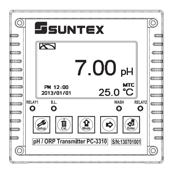
4. Configuration: 4.1 Illustration of front panel: 4.2 Keypad: In order to prevent inappropriate operation by others, before the parameter setting and calibration, the operation applies multi-keys and coding protection if necessary. Description of the key functions is in the following: In the parameter set-up mode, pressing this key allows you exit parameter set-up mode and back to Measurement mode. -
Page 22: Display
4.4 Display: 1. When the clean function is activated, the display shows “HOLD” and twinkles the description, “Clean Running”. At the same time, the WASH indicator LED lights up, and the transmitter automatically turns off Relay 1 and Relay 2 function. After finishing cleaning, the Relay 1 and Relay 2 will automatically be back to normal status. -
Page 23: Operation
5. Operation 5.1 Measurement mode: After all electrical connections are finished and tested, connect the instrument to the power supply and turn it on. The transmitter will automatically entering measurement mode with the factory default settings or the last settings from user. 5.2 Set-up menu: Please refer to the set-up instructions in Chapter 6. - Page 24 5.5.2 Calibration default value: Calibration type: TECH-No Cal Slope: - Asy: 0 mV Sensitivity: 100.0% Determination:1.0000 Calibration value: None data Auto back: Auto, 3 minutes Code set-up: OFF Note: The factory default of calibration presetting is “No Cal”, and the calibration value is “None”. It means that the user has not calibrated the sensor with the transmitter yet.
- Page 27 6.1 Entry of set-up menu In the measurement mode, pressing the two keys simultaneously allows you to enter the overview of current setting, and press to enter the set-up mode to modify the setting if necessary. “Measurement (Mode)” Press Press Press Press Press...
-
Page 28: Security Code Of Settings
6.2 Security code of settings After entering set-up mode, select “code” item, press to enter into code procedure. The code pre-setting is 1111. Note: The code of setting mode is prior to the code for calibration. That means that the code of setting mode can be used for the code of calibration mode. Press to confirm it. -
Page 29: Language
6.3 Language Enter Language setup menu, select the system language from English, Traditional Chinese and Simplified Chinese. Press to confirm it. Press Press to select tto select language type language type Press to confirm it. Enter “Measurement Mode” Setup... -
Page 30: Mode
6.4 Mode Enter setup of “Mode”. Select between “pH” or “ORP” measurement. Press to confirm it. Press to select between pH or ORP Press to confirm it. Enter ”Multi-Cal” Setup... -
Page 31: Multi-Cal
6.5 Multi-Cal Enter setup of multi-points calibration to set the number of calibration points. This function only applies to pH mode. Press to confirm it. Press to select the number of calibration points. There are 1~3 points to choose from. The factory default is 2 points. When the calibration reaches the number of setting points, the calibration procedure will automatically finish and display the calibration result. -
Page 32: Temperature
6.6 Temperature Enter setup of “Temperature” to select temperature compensation mode. Select from NTC(NT 30K), PTC(PT 1K) or MTC(Manual adjustment). Press to confirm it. Press Press to select to select Press to confirm it. Press to confirm it. Use standard thermometer to test If necessary, compare with the actual temperature of the the actual temperature value... -
Page 33: Relay 1
6.7 Relay 1 Enter setup of Relay 1. Select the item to turn on or turn of the relay 1 function. If you select to turn on the relay 1, then select for using relay 1 as “High set-point” alarm or “Low set-point” alarm. Set the value of set-point (SP) and Hysteresis (Hys.). -
Page 34: Relay 2
6.8 Relay 2 Enter setup of Relay 2. Select the item to turn on or turn of the relay 2 function. If you select to turn on the relay 2, then select for using relay 2 as “High set-point” alarm or “Low set-point” alarm. Set the value of set-point (SP) and Hysteresis (Hys.). -
Page 35: Clean
6.9 Clean Enter setup of “Clean” function. Select the icon to turn on or turn off the clean function. If you select “Auto” turning on, then set the timer of the clean function including automatically turning on time and turning off time, and set the Hysteresis value(Hys.). Note: When the clean function is turned on, if any value is set to be 0, the instrument will automatically turn off this function. -
Page 36: Analog Output 1 (Ph/Orp)
6.10 Analog output 1 (pH/ORP) Enter setup of Analog 1. Select 0~20mA or 4~20mA current output. Set the related value to the range of pH/ORP measurement. If the range of the pH/ORP measurement is to be set smaller, the resolution of current output is higher. When the measured value exceeds the higher range limit, the current will remain approximately 22mA output. -
Page 37: Analog Output 2 (Temperature)
6.11 Analog output 2 (Temperature) Enter setup of Analog 2. Select 0~20mA or 4~20mA current output. Set the related value to the range of temperature measurement. If the range of the temperature measurement is to be set smaller, the resolution of current output is higher. When the measured value exceeds the higher range limit, the current will remain approximately 22mA output. - Page 38 6.12 Date/Time(Clock) Enter setup of Date/Time(Clock). Set the “Year”, “Month”, “Date”, “Hour”, and “Minute” time. If you select to turn off the clock function, there will not display clock under measurement mode. The calibration time of calibration record will also show ”OFF” under calibration overview display. Note: The clock needs to be reset once encounters power failure.
-
Page 39: Sample Average Of Measurements (Digital Filter)
6.13 Sample average of measurements (Digital Filter) Enter the setup of Digital filter. You may select the number of sample to be averaged each time to become a reading which is gradually counted in order to increase the stability of measurement. Press to confirm it. -
Page 40: Backlight Settings
6.14 Backlight settings Enter setup of backlight display. According to your need, you can set the brightness of display(-2~2, dark~bright) and sensitivity of the sensitization sensor(-2~2, insensitive~sensitive). Where there is a keystroke, then activate the touch-on backlight function. Regardless of what kind of backlight mode, the touch-on function will activate the backlight. -
Page 41: Contrast Settings
6.15 Contrast settings Enter setup of display contrast. You can set the contrast of display according to your need.(-2, -1, 0, 1, 2, light to dark) Press to confirm it. Press to select display contrast level. Press to confirm it. Enter “Auto return mode (Return)”Setup... -
Page 42: Return
6.16 Return Enter setup of auto return mode (Return) to set the function that the instrument automatically exit the setup menu after a period of time without pressing any key. The “Manual Exit” means that it needs to exit setup menu manually, while “Auto” means that the display automatically exit the setup menu and back to measurement mode after a period of time without pressing any key. -
Page 43: Calibration
7. Calibration Block diagram of Calibration PC-3310 Cal. Info. Return Code TECH NIST Setting Setting Temp. adjust for Temp. adjust for Temp. adjust for Manual Input Auto first buffer (MTC first buffer (MTC first buffer (MTC Exit Password or ATC) -
Page 44: Enter Calibration Setup Menu
7.1 Enter calibration setup menu In the measurement mode, pressing the two keys simultaneously allows you enter the Calibration Information. If you do not need to re-calibrate the measurement system, press to go back to measurement mode. If you need to re-calibrate the system, press to enter to the calibration setup menu. -
Page 45: Security Password Of Calibration (Code)
7.2 Security password of calibration (Code) Select the Code (password) icon after entering calibration setup mode. Select to activate code function or not. The default Calibration setting code is “1100”. Press to confirm it. The first ‘0” of digits ‘0000” start to twinkle. -
Page 46: Ph Calibration
7.3 pH Calibration The instrument provides multi-point standard buffer solution calibration. You may decide how many points to calibrate the measurement system(up to 3-point). The principle is according to “Method of Least Squares”. Apply linear regression to calibration the electrode’s slope and zero point (Any, Offset or Zero point). -
Page 47: Definition Of Calibration Parameter
7.3.4 Definition of calibration parameter You can calibrate the electrode by one point or up to three points of standard solutions by any sequence. As different calibration point method is applied, the definition of the zero point and slope different. Calibration point Determination The showed calibration value Zero point (Asy, offset or Zero point)= Asy... -
Page 48: Tech, Nist Buffer Calibration
7.3.5 TECH, NIST buffer Calibration The procedure below is two points calibration of TECH buffer. (The procedure is same as NIST buffer mode.) First, enter the setup of Multi-points calibration and set the number of calibration point for 2. (See chapter 6.5 Multi-Cal) Then, go to Calibration menu and select TECH mode. -
Page 49: Any Calibration
7.3.6 Any Calibration The procedure below is two points calibration of Any mode. First, enter the setup of Multi-points calibration and set the number of calibration point for 2. (See chapter 6.5 Multi-Cal) Then, go to Calibration menu and select “Any” mode. Operate the instrument as follow procedure diagram. -
Page 50: Orp Calibration
7.4 ORP Calibration Under ORP measurement mode, enter calibration setup menu. Select Calibration icon, and adjust mV value. The adjustable range is from -300mV to 300mV. Press to confirm it. Put the ORP electrode into ORP standard solution. Press to adjust the main display value until it is equal to the desired mV value. -
Page 51: Return
7.5 Return Enter setup of auto return mode (Return) to set the function that the instrument automatically exits the setup menu after a period of time without pressing any key. The “Manual Exit” means that it needs to exit calibration setup menu manually, while “Auto” means that the display automatically exits the calibration setup menu and gets back to measurement mode after a period of time without pressing any key. -
Page 52: Error Messages (Error Code)
8. Error messages (Error code) Messages Reason Dispositions 1. Please replace by new buffers. Asy (Zero-point) exceeds 2. Maintain the electrode or Error1 upper/lower limitation change a new electrode, and make another calibration. 1. Please replace by new buffers. Slope exceeds upper/lower 2. -
Page 53: Maintenance
9. Maintenance Generally speaking, under normal operation, the transmitter needs no maintenance except regular cleaning and calibration of the electrode to ensure accurate and stable measurement and system operation. The cleaning cycle for the electrode depends on the pollution degree of the measurement sample. -
Page 54: Appendix
Appendix Table 1 TECH Buffers TECH buffers TEMP C Buffer 4.01 Buffer 7.00 Buffer 10.00 3.999 7.087 10.241 3.998 7.053 10.155 3.999 7.031 10.116 4.002 7.011 10.047 4.006 6.996 9.998 4.011 6.985 9.952 4.018 6.976 9.925 4.031 6.971 9.874 4.047 6.969 9.843 4.055... - Page 56 SUNTEX INSTRUMENTS CO., L TD. 13F, No. 31, Lane 169, Kangning St., Xizhi Dist., New Taipei City, Taiwan (R.O.C.) Tel: 886-2-2695-9688 Fax: 886-2-2695-9693 www.suntex.com.tw/en e-mail: suntex@ms1.hinet.net 5040C PC-3 10/Technical data subject to alternations/ Quality Systems ISO 9001/201...
Need help?
Do you have a question about the PC-3310 and is the answer not in the manual?
Questions and answers