Advertisement
Quick Links
1.1 General
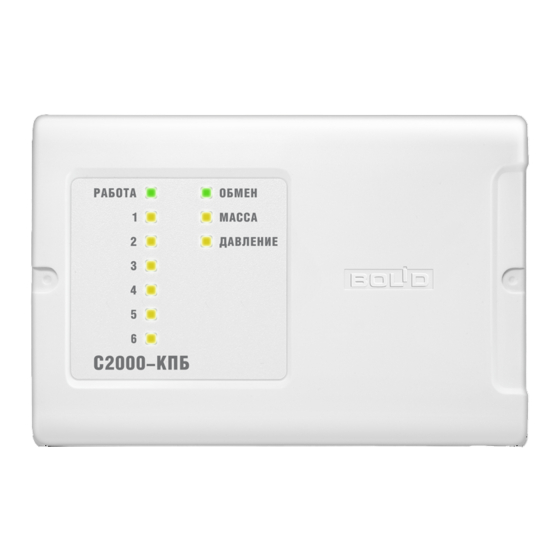
1.1.1 This Instruction Manual describes how to operate and maintain the S2000-KPB Executive
Module (hereinafter referred to as the module).
1.1.2 The module is designed to operate as part of fire alarm systems, fixed fire-fighting systems,
access control systems, CCTV in cooperation with an S2000-ASPT Fire Alarm and Extinguishing
Control Panel and an S2000 / S2000M Console or PC.
1.1.3 The module is designed to control executive devices (light panels, sirens, video cameras,
electromagnet locks etc.) as well as clean agent suppression systems and fire-fighting equipment in
gas, dry powder, and aerosol fire-fighting systems.
1.1.4 The module is designed to be installed on a vertical surface inside the protected premises
closely to the executive devices. The module is designed for round-the-clock operation.
1.1.5 The module must not be used in aggressive medium or dust condition, or in .explosion-
hazardous premises.
1.2 Specifications
1.2.1 Power Supply
1.2.2 Power Inputs
1.2.3 Consumed Current (without executive devices):
–
At 12 V power voltage
–
At 24 V power voltage
1.2.4 Consumed Current in Quiescent Mode (all
outputs are switched off):
–
At 12 V power voltage
–
At 24 V power voltage
1.2.5 Outputs:
–
Switching Voltage
–
Switching Current
–
Circuit Failure Monitoring Current
1.2.6 Maximum Total Switched Current of the Module – 3 А
1.2.7 Alarm Loops
1.2.8 Resistance of the alarm loop wires without
additional resistances
1.2.9 Leakage Resistance Between Alarm Loop Wires
or Each Wire and Ground
1.2.10 Overall Dimensions
1.2.11 Weight
1.2.12 Operating Temperatures
S2000-KPB
EXECUTIVE MODULE
Version
INSTRUCTION MANUAL
1
TECHNICAL DESCRIPTION
2.04
– An external dc power supply with the
power voltage between 10.2 V dc and
28.4 V dc (RIP-12, RIP-24)
– Two
– 130 mA max;
– 70 mA max
– 45 mA max;
– 25 mA max.
– Six
– 10.2 dc to 28.4 V dc
(from the power supply of the module)
– 2 A max
– 1.5 mA max
– Two
– 100 Ohm max
– 50 kOhm min
– 156 mm × 107 mm × 36 mm max
– 0.3 kg max
– Minus 30 to +55°С
1
Advertisement

Subscribe to Our Youtube Channel
Related Manuals for bolid S2000-KPB


Summary of Contents for bolid S2000-KPB
- Page 1 TECHNICAL DESCRIPTION 1.1 General 1.1.1 This Instruction Manual describes how to operate and maintain the S2000-KPB Executive Module (hereinafter referred to as the module). 1.1.2 The module is designed to operate as part of fire alarm systems, fixed fire-fighting systems, access control systems, CCTV in cooperation with an S2000-ASPT Fire Alarm and Extinguishing Control Panel and an S2000 / S2000M Console or PC.
- Page 2 1.2.13 Ingress Protection Rating (if wall mounted) – IР30 1.2.14 Pre-Operation Time – 3 s 1.3 Standard Delivery 1) S2000-KPB Executive Module – 1 pc. 2) Instruction Manual – 1 pc. 3) DIN 7982 Flat Head Tapping Screw with Cross Drive 2.2×6.5 –...
- Page 3 Figure 2. An Example of Adjusting an Auxiliary Programmable Alarm Loop Change of states of an alarm loop is defined only by change of its resistance and doesn’t depend on other alarm loop parameters and network controller commands. The integration time in case of changing a state is 300 ms.
- Page 4 Status Light Color Indicator Behavior Fire Equipment Trouble AC Power Failed Too High Level Flashes within 250 ms once per Heat Sensor Failed Yellow second Tamper Alarm Battery Failed Too Low Level Fire Alarm Yellow Flashes twice per second Fire Alarm 2 Loop Open Failure Yellow Two flashes within 250 ms every 2 s...
- Page 5 – In case of a short output failure in the moment of switching on the output, the output is not switched on. If the module is connected to the internal interface RS-485-2 of an S2000-ASPT device, the S2000-KPB module operates to expand discharge circuits. Centralized control of individual outputs of the module by the S2000M console in such case is disabled.
- Page 6 Circuit’s Output’s Indicator Behavior Condition Condition Open Failure Double flashes in yellow once per two seconds Short Failure Flashes in yellow once per two seconds 2.1.3 Communicating Data Over the RS-485 Interface The module receives commands and transmits messages to the network controller over the RS-485 interface.
- Page 7 To change configuration parameters of the module, an IBM compatible PC and one of the Bolid manufactured interface converters (such as PI-GR, S2000-PI, S2000-USB etc.) are to be used. The configuration parameters are changed by means of UProg Configuration Tool of version 4.1.0.3 or...
- Page 8 In the Device Failed mode READY and COM LEDs flash alternately while other indicators are lit steady. If the module enters the Device Failed mode on switching on, update its firmware by means of ORION_PROG (download the last version from the Download section at http://bolid.ru) or return it to the manufacturer. OPERATIONAL DIRECTIVES 3.1 Safety Precautions...
- Page 9 3. If an output is not in use, a 1kOhm - 0.5 W resistor can be used instead of the load connection module. 4. Normally open and normally closed detectors can be combined and brought into the same circuit if only a single detector can be in activated status. Figure 3. S2000-KPB Wiring Diagram...
-
Page 10: Performance Instructions
PERFORMANCE INSTRUCTIONS 4.1 When you select a power supply be sure it can provide the electric current enough to power all the executive devices connected to the module. 4.2 The power supply should be located at such distance from the module that the resistance R the wires between the power supply and the module (see Figure 4) meets the following requirement: –... -
Page 11: Maintenance
[Ohm] (see Clause 4.2); is for the resistance of wires between the S2000-KPB and the fixed fire-fighting system, [Ohm] (see Clause 4.2); is for the effective resistance of the exploder (bridgewire), [Ohm]. - Page 12 How to generate the command or call the event to activate the control command for each used output. 5.3.2 Open the cover of the S2000-KPB module removing the tamper label if necessary. 5.3.3 WARNING: If the module is connected to clean agent suppression modules or other executive devices which must not be activated during the inspection, carry out the steps 5.3.4 –...
- Page 13 5.3.18 One-by-one, connect to the “loop 1” and “loop 2” terminals the resistors nominal values of which are defined in the configuration of the S2000-KPB. 5.3.19 Ensure that the control device (the network controller) displays the events which correspond to each resistance value and MASS and PRES indicators operate as shown in Table 1.
-
Page 14: Overall And Mounting Dimensions
OVERALL AND MOUNTING DIMENSIONS ZAO NVP Bolid, 4 Pionerskaya Str., Korolev 141070, Moscow Region, Russia Phone/fax: +7 495 775-7155 Email: info@bolid.ru Technical Support: support@bolid.ru http://bolid.ru...
Need help?
Do you have a question about the S2000-KPB and is the answer not in the manual?
Questions and answers