Advertisement
Quick Links
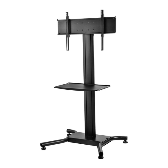
SS560M
FEATURES
Continous vertical
adjustment for perfect
viewing height
Incremental tilt of -2°, 0°
and +5° makes it simple
to set multiple angles for
preferred viewing and
aids in reducing screen
glare
Metal or tinted tempered
glass shelf provides
storage space for A/V
components. These
shelves are designed to
hold up to 50 pounds
each, ensuring equipment
and user safety.
Internal cable
management for clean,
clutter free look
Feet with a hard plastic
base with steel casing
Flat Panel Stand
for 32" to 65" Flat Panel Displays
The Flat Panel Stand is designed to provide ideal display viewing position, centralize audio video
components and match the décor of any environment. The full line of accessories enables each
stand to be fully tailored to meet specific requirements; whether video conferencing from a
boardroom or presenting on a trade show floor. And the internal cable management hides all
the AV cabling, providing a clean, clutter-free look.
Display size: 32" - 65"
Max load: 150lb (68kg)
INCREMENTAL TILT
Incremental tilt of -2°, 0°
and +5° makes it simple
to set multiple angles for
preferred viewing and aids
in reducing screen glare
VERTICAL ADJUSTMENT
Continous vertical adjustment
for perfect viewing height
COMPONENT PLACEMENT
Metal or tinted tempered glass
shelf provides storage space for
A/V components. These shelves are
designed to hold up to 50lb each,
ensuring equipment and user safety.
Internal cable
management
Advertisement

Related Manuals for peerless-AV SS560M


Summary of Contents for peerless-AV SS560M
- Page 1 Flat Panel Stand SS560M for 32" to 65" Flat Panel Displays The Flat Panel Stand is designed to provide ideal display viewing position, centralize audio video components and match the décor of any environment. The full line of accessories enables each stand to be fully tailored to meet specific requirements;...
- Page 2 A R C H I T E C T S S P E C I F I C A T I O N S Flat Panel Stand stand shall be a Peerless model SS560M/G and shall be installed where indicated on the plans. It shall be constructed of heavy gauge cold rolled steel...
- Page 3 Installation and Assembly: 32" - 65" Flat Panel Display Stand Models: SS560M Max UL Load Capacity: 150 lb (68 kg) display 50 lb (22.7 kg) per shelf 2300 White Oak Circle • Aurora, Il 60502 • (800) 865-2112 • Fax: (800) 359-6500 • www.peerlessmounts.com...
-
Page 4: Table Of Contents
NOTE: Read entire instruction sheet before you start installation and assembly. WARNING • Do not begin to install your Peerless product until you have read and understood the instructions and warnings contained in this Installation Sheet. If you have any questions regarding any of the instructions or warnings, for US customers please call Peerless customer care at 1-800-865-2112, for all international customers, please contact your local distributor. -
Page 5: Parts List
Before you begin, make sure all parts shown are included with your product. Parts may appear slightly different than illustrated. Parts List Qty. Part Number Description A screen mount bracket 201-1156 B hook plate 201-1157 201-1158 C shelf support D base 009-1223 E universal plate 201-1110... - Page 6 Parts List continued Some parts may appear slightly different than illustrated. 4 of 41 ISSUED: 02-25-11 SHEET #: 009-9052-2 10-30-11...
-
Page 7: Assembling C Art
Insert right leg (S) into base housing (D) as shown in fi g. 1.1. Then align holes in right leg with holes in base housing (D). Fasten base housing to right leg using two 3/8-16 x 1.5" bolts (W) and two joint connectors (V). Tighten using 3/16"... - Page 8 Attach upright (G) to base (D), as shown in fi g 3.1 using three 3/8-16 x 2.5" socket screws (L) and M10 x .402ID lock washers (X). Tighten screws using 7/32" allen wrench (M). NOTE: Be sure cord management holes are in the confi guration shown in fi g 3.2. fi...
- Page 9 Slide shelf support (C) onto upright (G) so that 1/4-20 nuts (J) slide into slots of upright (G) as shown in fi gure 5.1 and detail 1. Slide shelf support to desired height, level, then tighten 1/4-20 x 12mm screws (I) using 4 mm allen wrench (N).
- Page 10 Attaching Metal Shelf Attach shelf pan (P) to shelf support (C) using six 8/32 nylock nuts (O) as shown below. Use an adjustable wrench to tighten six 8/32 nylock nuts (O). WARNING • This shelf is intended for use with equipment weighing no more than 50 lbs.
- Page 11 Loosely attach six 1/4-20 x 12 mm screws (I) and Slide display mount bracket (A) onto upright (G) so 1/4-20 nuts (J) to display mount bracket (A). that 1/4-20 nuts (J) slide into slots of upright (G) as shown in fi gure 8.1 and detail 2. Slide display mount bracket to desired position, level, then tighten...
-
Page 12: Attaching Universal Adapter Plate
Attaching Universal Adapter Plate or Dedicated Adapter Plate Attach Universal Plate (E) or Dedicated Adapter Attach hook plate (B) to display mount bracket (A). Plate to hook plate (B) using four M10 x 15 mm socket screws (OO). Tighten screws using 6 mm allen wrench (Q). -
Page 13: Installing Adapter Brackets
Installing Adapter Brackets to Universal Plate WARNING • Tighten screws so adapter brackets are fi rmly attached. Do not tighten with excessive force. Overtightening can cause stress damage to screws, greatly reducing their holding power and possibly causing screw heads to become detached. - Page 14 For Flat Back Display Begin with the shortest length screw, hand thread through multi-washer and adapter bracket into display as 14-1 shown below. Screw must make at least three full turns into the mounting hole and fi t snug into place. Do not over tighten.
-
Page 15: Cord Management
Mounting and Removing Flat Panel Display WARNING • Always use an assistant or mechanical lifting equipment to safely lift and position the plasma television. Hook adapter brackets (F) onto universal plate (E), then slowly swing display in as shown. Turn screws of adapter plate (F) clockwise at least six times to prevent display from being removed as shown in detail 4. - Page 16 LIMITED FIVE-YEAR WARRANTY Peerless Industries, Inc. (“Peerless”) warrants to original end-users of Peerless® products will be free from defects in material and workmanship, under normal use, for a period of fi ve years from the date of purchase by the original end-user (but in no case longer than six years after the date of the product’s manufacture). At its option, Peerless will repair or replace, or refund the purchase price of, any product which fails to conform with this warranty.
- Page 17 Français GARANTIE DE CINQ ANS Peerless Industries, Inc. (« Peerless ») garantit aux utilisateurs fi naux d’origine des produits PeerlessMD que lesdits produits ne présenteront aucun défaut de matériau ou de main-d’œuvre, dans la mesure où ils sont utilisés normalement, pendant une période de cinq ans à compter de la date d’achat par l’utilisateur fi nal d’origine (mais en aucun cas plus de six ans après la date de fabrication du produit).
Need help?
Do you have a question about the SS560M and is the answer not in the manual?
Questions and answers