Sign In
Upload
Manuals
Brands
Daitsu Manuals
Dehumidifier
FDLA-40
Daitsu FDLA-40 Manuals
Manuals and User Guides for Daitsu FDLA-40. We have
1
Daitsu FDLA-40 manual available for free PDF download: Installation, Operation & Service Manual
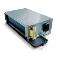
Daitsu FDLA-40 Installation, Operation & Service Manual (322 pages)
Brand:
Daitsu
| Category:
Dehumidifier
| Size: 8 MB
Table of Contents
Table of Contents
3
General Description
6
General Specifications
7
A.2.1. 2-Pipe Systems
7
A.2.2. 4-Pipe Systems
9
Coil Data
10
Dimensional Drawings
11
Sound Data
12
Valve Information (Optional)
14
A.6.1. On/Off Ball Valve Model
14
A.6.2. Modulating Valve Model
15
Safety Precautions
16
Location
17
Installation Procedures
17
Insulation
19
Air Duct Connection
19
Piping Connections
19
Electrical Connection
20
General Maintenance
22
Regular Maintenance
22
Filter Cleaning
22
Fan Motor Assembly Maintenance
22
Coil Direction Interchange
23
Electric Heater Replacement
23
I/O Port Definitions
24
Wiring Diagrams
25
D.2.1. Standard AC-S1 Control PCB
25
D.2.2. Master Slave Networking Wiring Diagram
26
Configuration Settings
27
D.3.1. Fan Coil Unit ON/OFF
28
D.3.2. Auto Restart
28
Control Logics for 2-Pipe System
29
D.4.1. with Valve Configuration
29
D.4.2. Without Valve Configuration
31
Control Logics for 4-Pipe System
32
Sleep Mode
34
Auto Fan Speed
34
On/Off Switch on LED Display Panel
35
Electric Heater Safety Switch
35
Low Temperature Protection of Indoor Coil in Winter
35
Buzzer
35
Auto Restart
35
LED Display and Error Description
36
LED Display on Master/Slave Connection
37
Master-Slave Network
38
D.15.1. Master Unit Control Settings
38
D.15.2. Master Slave Network Setup
39
D.15.3. Master Slave Communication Method
41
Open Modbus Protocol
42
Remote Handset
45
Wired Wall Pad Controller
46
General Description
57
General Specification
58
2-Pipe Systems
62
Coil Data
62
Valve Information ( Optional Parts )
64
Safety Precautions
65
Installation
66
Location
66
Unit Installation
66
How to Interchange Left/Right Sided Connection
67
Pipe Connections
68
Maintenance
70
General Maintenance
70
Monthly Maintenance
70
Filter Cleaning
70
Fan -Motor Assembly Maintenance
71
Control Specifications for Full PCB Control: SK-NCPDWH-001B ~S Configuration: Full Control PCB
72
I/Oport Definitions
72
Wiring Diagram
74
Configuration Settings
76
Control Logic for 2-Pipe System
78
With Valve Configuration
78
Without Valve Configuration
81
Control Logics for 4-Pipe System
83
Sleep Mode
85
Auto Fan Speed
86
Swing/Louver
86
Buzzer
86
Auto Restart
86
O N /Off Switch O N the Front Panel
86
Drain Pump
87
Float Switch
87
Electric Heater Safety Switch
87
Led Indication and Error Description
87
Led Indication O N Master /Slave Connection
89
Networking System
90
Master -Slave Network
90
Master - Slave Network Setup
91
Master - Slave Communication Method
94
Open Modbus Protocol
95
User Interface
99
Remote Handset
99
Wired Wall Pad
100
Wall Pad Operation Guidelines
101
Sensor Resistance R-T Conversion Table
104
Troubleshooting
106
Spare Parts and Sub-Assembly Descriptions
107
Module Layout
109
Technical Data
117
General Description
117
General Specifications
118
2-Pipe Systems
118
4-Pipe Systems
120
Coil Data
121
Dimensional Drawings
122
Sound Power Data
126
Valve Information (Optional Parts)
132
Actuator
133
Installation
134
Safety Precautions
134
Standard Configurations and Accessories
135
Operating Limits
136
Before Installation
136
Installation Location
137
False Ceiling Clearance
137
Condensate Drainage Connection
137
External Drain Pan Installation
138
Water Connections and Valve Configurations
139
Fresh Air Renewal Connection
141
Branch Duct Connection
143
Suspension Bolts Layout and Ceiling Opening
144
Interconnecting Wiring
148
Mounting Front Panel Assembly
149
Start-Up
149
Maintenance
150
For Units out of Use for Extended Period
150
Extra Maintenance
150
Filter Removal
150
Air Vent and Water Purge Valve
151
Fan Speed Customization
151
Motor and Fan Blower Replacement
152
Condensate Pump Kit Replacement
153
Control Box Replacement
153
Electric Heater Installation
154
Control Specifications: Complete Control PCB - EC-S1 Control
155
I/O Port Definitions
155
Wiring Diagrams
156
Standard EC-S1 Control PCB
156
Master Slave Networking Wiring Diagram
157
Configuration Settings
158
Control Logic for 2-Pipe System
160
With Valve Configuration
160
Without Valve Configuration
163
Control Logic for 4-Pipe System
164
Sleep Mode
166
Auto Fan Speed
166
Modulating Valve Control under Energy Saving Mode
166
Louver
166
Buzzer
167
Auto Restart
167
On/Off Switch on the LED Panel
167
Drain Pump
167
Float Switch
167
Electric Heater Safety Switch
168
Low Temperature Protection of Indoor Coil in Winter
168
LED Display and Error Description
169
LED Display on Master/Slave Connection
170
Networking System
171
Master-Slave Network
171
Master Control Unit Settings
171
Master-Slave Network Setup
172
Master-Slave Communication Method
174
Open Modbus Protocol
175
Control Specifications: Flexible Function PCB - EC-W1 Control
178
Features
178
I/O Port Definitions
178
Onboard Configurations
178
Wiring Diagrams
179
Standard EC-W1 Control PCB
179
Control Logic Specifications
180
Unit Power ON/OFF
180
Alarm Protection and Error Display
180
Drain Pump Operation
180
Louver Control
180
Modulating Signal Input
180
Low Temperature Protection of Indoor Coil in Winter
180
LED Display and Error Description
181
User Interface
182
Remote Handset
182
Wired Wall Pad Controller
183
Sensor Resistance R-T Conversion Table
187
Troubleshooting
189
General Description
196
Technical Data
197
General Specification
197
FMCD-V-EC Series 3-Speed Specifications
197
Coil Data
199
2-Pipe Systems
199
Dimensional Drawings
200
Valve Information
202
2-Way Valve Body
202
Installation of High -Wall Unit
203
Selecting a Location
203
Mounting Plate Dimensions
204
Installing the Mounting Plate
205
Drilling the Condensate Drainage Hole
205
Installing the Hydronic Unit
206
Drainage Piping Works
206
Unit Maintenance and Preparation
207
Opening and Closing of Lift-Up Grille Cover
207
Removing Front Cover Assembly
207
Air Purging
207
Wiring Connections
207
Pipe Connections with Valve
208
Control Specifications
209
SK-NCSWC-001 Complete Function FCU Controller
209
Abbreviations
209
Definition of Input/Output
209
Wiring Diagram SK-NCSWC-001
210
Configuration Settings
211
Control Logics for 2-Pipe System
213
Control Logics for 4-Pipe System
218
Auto Fan Speed
221
Louver
222
Buzzer
222
D.1.10. Auto Restart
222
D.1.11. Operation of Control Panel on High-Wall Unit
222
Led Lights
223
LED Indication and Error Description
224
LED Indication on Master/Slave Connection
225
Networking System
226
Master-Slave Network
226
Master-Slave Network Setup
227
Master-Slave Communication Method
230
Unit Network Wiring Scheme
231
SK-NCSWC-002 Limited Function FCU Controller
232
Definition of Input/Output
232
Wiring Diagram SK-NCSWC-002
233
Onboard Configuration
234
Control Logic
235
LED Indication
235
Error Description
235
Open Modbus Protocol
236
Users Interface
240
Remote Control Handset
240
Wired Wall Pad
241
Wall Pad Display
241
Wall Pad Operation Guidelines
242
EC Unit RPM Setting
245
Sensor Resistance R-Tconversion Table
246
Troubleshooting Guide
248
Technical Data
255
Introduction
255
Unit Appearance
256
A.3. General Specification
257
2-Pipe Systems
257
A.3.2. 4-Pipe Systems
261
A.4. Coil Data
262
A.4.2. 4-Pipe Systems
262
Dimensional Drawings
263
Valve Information
265
2-Way 3/4" Valve Body
265
2-Way 1/2" Valve Body
266
Safety Precautions
267
Installation
268
Installation Procedure
268
Piping Connections
270
How to Interchange Left / Right Side Connection
271
Electrical Connection
272
Valve and External Drain Pan Installation
272
Maintenance
274
General Maintenance
274
Monthly Maintenance
274
Filter Installation & Cleaning
274
Fan-Motor Assembly Maintenance
275
Control Specifications: SK-NCPFWB-001-ECM ~S Configuration: Full Control PCB
276
I/Oport Definitions
276
Wiring Diagram
278
Configuration Settings
280
Control Logics for 2-Pipe System
282
With Valve Configuration
282
Without Valve Configuration
285
Control Logic for 4-Pipe System
287
Sleep Mode
289
Auto Fan Speed
290
Modulating Valve Control under Energy Saving Mode
290
Swing / Louver
290
Uto Restart
291
Panel
291
Pump
291
Switch
291
Description
292
Master /Slave Connection
293
Networking System
294
Master -Slave Network
294
Master - Slave Network Setup
295
Master - Slave Communication Method
298
Open Modbus Protocol
299
Control Specifications: SK-NCPFWB-002-ECM ~W Configuration: Limited Function PCB
303
Features
303
I/Oport Definitions
303
Onboard Configuration
304
Wiring Diagrams
305
Standard Unit Wiring Diagram of SK-NCPFWB-002-ECM
305
Zone Control Wiring Diagram 1 (ON/OFF Thermostat)
306
Example for 2-Pipe PCU with EC-Mini PCB + EC Thermostat + Modulating Valve
307
Control Logic Specification
308
Unit Power ON/OFF
308
Alarm Protection and Error Display
308
Drain-Pump Run Management
308
Swing and Louver Control
308
Modulating Signal Input
308
Led Indication and Error Description
309
User Interface
310
Remote Handset
310
Wired Wall Pad
311
Wall Pad Operation Guidelines
312
EC Unit RPM Setting
315
Sensor Resistance R-T Conversion Table
316
Troubleshooting
318
Descriptions
319
Auxiliary External Drain Pan
321
ABS Supporting Feet
321
Advertisement
Advertisement
Related Products
Daitsu FDLA-09
Daitsu FDLA-12
Daitsu FDLA-15
Daitsu FDLA-18
Daitsu FDLA-24
Daitsu FDLA-30
Daitsu FDLA-34
Daitsu FDLA-54
Daitsu FDLA-60
Daitsu FSTD SLIM - EC FLEX Series
Daitsu Categories
Air Conditioner
Dehumidifier
Controller
Remote Control
Heat Pump
More Daitsu Manuals
Login
Sign In
OR
Sign in with Facebook
Sign in with Google
Upload manual
Upload from disk
Upload from URL