
Related Manuals for horiba LAQUA 2000 Series


Summary of Contents for horiba LAQUA 2000 Series
- Page 1 Instruction Manual Benchtop pH/ORP/ION/Conductivity Meter LAQUA-PH2000 LAQUA-ION2000 LAQUA-EC2000 LAQUA-PC2000...
- Page 3 HORIBA Advanced Techno Co., Ltd. warrants that the product shall be free from defects in material and workmanship and agrees to repair or replace free of charge, at option of HORIBA Advanced Techno Co., Ltd., any malfunctioned or damaged product attributable to responsibility of HORIBA Advanced Techno Co., Ltd.
- Page 4 MEMO...
- Page 5 Regulations ■ Regulations • EU and UK Regulations • Conformable Standards This equipment conforms to the following standards: EMC: EN61326-1 Class B, Basic electromagnetic environment Safety: EN61010-1 RoHS: EN IEC 63000 9. Monitoring and control instruments including industrial monitoring and control instruments EMC: BS EN 61326-1 Class B, Basic electromagnetic environment...
- Page 6 • Authorised Representative in EU Europe GmbH HORIBA Hans-Mess-Str.6, D-61440 Oberursel, Germany • Authorized Representative in UK HORIBA UK Limited Kyoto Close Moulton Park NN3 6FL Northampton, UK Tel: +44 01604 542500 • FCC Rules FCC Compliance Statement This device complies with part 15 of the FCC Rules. Operation is subject to the following two conditions: (1) This device may not cause harmful interference, and (2) this device must accept any interference received, including interference that may cause undesired operation.
- Page 7 Regulations Note This equipment has been tested and found to comply with the limits for a Class A digital device, pursuant to part 15 of the FCC Rules. These limits are designed to provide reasonable protection against harmful interference when the equipment is operated in a commercial environment.
- Page 8 Regulations Name and amount of hazardous substance used in a product 有害物质 Hazardous substances 多溴二苯醚 六价铬 多溴联苯 Poly 部件名称 汞 镉 Hexa- Poly 铅 Unit name Mer- Cad- bromo- Lead valent bromobi- cury mium diphenyl (Pb) chromium phenyl (Hg) (Cd) ether (Cr (VI)) (PBB)
- Page 9 For Your Safety ■ For Your Safety • Hazard classification and warning symbols Warning messages are described in the following manner. Read the messages and follow the instructions carefully. • Hazard classification This indicates an imminently hazardous situation which, if not avoided, will result in death or serious injury.
- Page 10 For Your Safety • [DEU] Sicherheitsinformation Lesen Sie vor der Verwendung des Produkts unbedingt diese Anleitung, um den ordnungsgemäßen und sicheren Betrieb des Produkts zu gewährleisten. Bewahren Sie die Anleitung sicher auf, damit sie bei Bedarf jederzeit zur Hand ist. Die Inhalt dieser Anleitung können ohne Vorankündigung geändert werden.
- Page 11 For Your Safety • Ambiente di installazione Questo prodotto non è stati progettati per essere utilizzati in ambienti industriali, secondo la norma EN61326-1. In un ambiente industriale, le interferenze elettromagnetiche potrebbero causare un malfunzionamento del prodotto. Per utilizzare il prodotto in tali ambienti, all'utente potrebbe essere richiesto di adottare le contromisure necessarie.
- Page 12 For Your Safety • [POL] Informacje dotyczące bezpieczeństwa Przed przystąpieniem do użytkowania tego produktu należy dokładnie zapoznać się z niniejszą instrukcją, aby zapewniona była prawidłowa i bezpieczna eksploatacja produktu. Instrukcję przechowywać w bezpiecznym miejscu, aby w razie potrzeby była zawsze dostępna. Treść...
- Page 13 For Your Safety • [JPN] 安全情報 ご使用になる前に、本書を必ずお読み ください。お読みになった後は必要なときに すぐに取 り出せるように大切に保管 して ください。 本書に記載 されている内容は予告な く 変更 される場合があります。あらか じめご了 承 ください。 • 設置環境 本製品は、EN61326-1 で定義 される工業環境で使用することを想定 した製品では ありません。 工業環境においては、電磁妨害の影響を受ける可能性があり、その場合には使用者 が適切な対策を講ずることが必要 となることがあります。 本製品は、EN61010-1 で定義 される以下の環境用に設計 されています。 - 過電圧カテゴリー II - 汚染度 2...
- Page 14 For Your Safety • Safety precautions This section provides precautions for using the product safely and correctly and to prevent injury and damage. The terms of DANGER, WARNING and CAUTION indicate the degree of immanency and hazardous situation. Read the precautions carefully as it contains important safety messages.
- Page 15 Product Handling Information ■ Product Handling Information • Operational Precautions (instrument) • Only use the product including accessories for their intended purpose. • Do not drop or physically impact the instrument. • The instrument is made of solvent-resistant materials but that does not mean it is resistant to all chemicals.
- Page 16 Manual Information ■ Manual Information • Description in this manual Note This interprets the necessary points for correct operation and notifies the important points for handling the product. This indicates reference information.
-
Page 17: Table Of Contents
Contents ■ Product Overview............1 ............ ● Package Content ............● Key Features ■ Basic Operations............6 ........● Turning On the Instrument ........● Connecting an Electrode ........ ● Changing the Operation Mode ....● Changing the Measurement Parameter ■ Calibration..............10 ............ - Page 18 Contents ■ Setup................. 28 ..● P1 pH Setup............28 ..● P1 Ion Setup............. 33 ............● P1 COND Setup ............● P2 TDS Setup ............● P3 SAL Setup .............. ● Data Setup ............● General Setup .............
-
Page 19: Product Overview
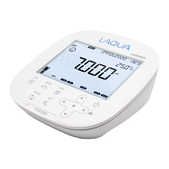
Product Overview ■ Product Overview The LAQUA 2000 series benchtop meters are optimized for laboratory measurement, and allow you to measure pH, ORP/mV, ion, conductivity, resistivity, TDS, salinity and temperature. This section describes the package content, key features and product components of LAQUA 2000 series benchtop meters. -
Page 20: Key Features
Product Overview ● Key Features • Large monochrome LCD • Integrated electrode holder (up to 2 electrodes) that can be attached to either side of the meter • Simple user interface and single parameter display • 2000 Memory data • Real time clock •... - Page 21 Product Overview ● Display Name Function Displays the current operation mode (Setup, Calibration, Status Icon Measurement and Data mode) Displays the measured parameters like pH, mV, ION, COND, Parameters Res, TDS and Sal Smiley icon and sound indicate value is stable for documentation in Auto Stable and Auto Hold modes Appears when the measured value display is stable and fixed in Auto Hold mode...
- Page 22 Product Overview Name Function Displays the calibration method Displays the pH buffer groups, pH buffer values and conductivity standards ● Electrode Sensitivity Level Conductivity Salinity Electrode pH Average Ion Average Average Calibration Icon Slope Slope Factor Calibration Factor Excellent 95.0 to 105.0% 90.1 to 199.9% 0.909 to 1.111 0.9 to 1.1...
- Page 23 Product Overview ● Keypad Operation Keypad Name Function Switches from the measurement mode to the calibration mode. CAL key Starts calibration in the calibration mode. Switches from the operation mode to the measurement mode. MEAS key Releases the fixed measurement value mode in the auto hold mode and begins a fresh measurement.
-
Page 24: Basic Operations
This section describes the basic operations such as turning on the instrument, connecting an electrode, and changing the operation modes and measurement parameters of LAQUA 2000 series benchtop meters. ● Turning On the Instrument 1. Insert the AC adapter cable by fitting with the AC adapter jack. -
Page 25: Changing The Operation Mode
Basic Operations ● Changing the Operation Mode You can change the operation mode to four available modes depending on the purpose of use. The status icon indicates the current mode. Icon Name Function Measurement Performs measurement. mode Calibration mode Performs calibration. Data mode Displays the saved data. - Page 26 Basic Operations You can change the operation mode using the corresponding key: • Measurement mode: Press the key to change to the measurement mode. • Calibration mode: In the measurement mode, press the key to change to the calibration mode. •...
-
Page 27: Changing The Measurement Parameter
Basic Operations ● Changing the Measurement Parameter This instrument measures pH, ORP/mV, ion, conductivity, resistivity, TDS, and salinity. For measurement, an electrode corresponding to the measurement parameter is required. In the measurement mode, the measurement parameter can be changed by pressing the key. -
Page 28: Calibration
Calibration ■ Calibration This section describes the calibration procedures using LAQUA 2000 series benchtop meters and electrodes. ● pH Calibration Calibration is necessary for accurate pH measurement. To perform pH calibration using PH2000, ION2000, or PC2000 meter, follow the procedure detailed below: Prerequisites •... - Page 29 pH Calibration Auto Calibration 1. After placing the pH electrode in pH buffer, press the CAL key. 2. The selected pH buffer group (USA, NIST, NIST2 or DIN) appears on the meter screen and meter starts checking various calibration values with a blinking on screen.
- Page 30 pH Calibration Manual Calibration 1. After placing the pH electrode in pH buffer, press the CAL key. 2. The selected CUST pH buffer group appears on the meter screen. 3. Wait for the to stabilize. When it stabilizes, there will be a sound indicating that reading is stable.
-
Page 31: Orp/Mv Calibration
ORP Calibration ● ORP/mV Calibration Calibration is necessary for accurate ORP measurement. To perform ORP calibration using PH2000, ION2000, or PC2000 meter, follow the procedure detailed below: Prerequisites • Clean the ORP electrode with DI (deionized) water and wipe it with tissue paper. •... - Page 32 ORP Calibration Calibration 1. After placing the ORP electrode in ORP standard solution, press the key to switch to mV mode. 2. Press the key. 3. Meter starts reading mV values. 4. Wait for the to stabilize. When it stabilizes, there will be a sound indicating that reading is stable.
-
Page 33: Ion Calibration
Ion Calibration ● Ion Calibration Calibration is necessary for accurate ion measurement. To perform ion calibration using ION2000 or PC2000 meter, follow the procedure detailed below: Prerequisites • If ion electrode is new or stored for long period, condition it first. Refer to the ion electrode manual for the electrode preparation and conditioning procedures. - Page 34 Ion Calibration • To abort an ongoing calibration process at any point of time, press the key. • It is recommended to clear the previous calibration data before performing calibration. For erasing the calibration data, refer to “P1.3 Calibration Clear Setup” on page 37.
- Page 35 Ion Calibration Calibration 1. After placing the ion electrode in standard solution, press the key. 2. Wait for to stabilize. When it stabilizes, there will be a sound indicating that reading is stable. 3. Press keys to enter the standard solution concentration and adjust the unit.
-
Page 36: Conductivity Calibration
Conductivity Calibration ● Conductivity Calibration Calibration is necessary for accurate electrical conductivity measurement. To perform conductivity calibration using EC2000 or PC2000 meter, follow the procedure detailed below: Prerequisites • Clean the conductivity electrode with DI (deionized) water and wipe it with tissue paper. •... - Page 37 Conductivity Calibration Auto Conductivity Calibration 1. After placing the conductivity electrode in the conductivity standard, press the key. 2. Meter displays AUTO CAL and starts measuring various calibration values with a blinking on screen. 3. Wait for the to stabilize. When it stabilizes, there will be a sound indicating that reading is stable.
- Page 38 Conductivity Calibration Manual Conductivity Calibration 1. After placing the conductivity electrode in the conductivity standard, press the key. 2. Meter displays MANUAL CAL and starts measuring with a blinking on screen. 3. Wait for the to stabilize. When it stabilizes, there will be a sound indicating that reading is stable.
-
Page 39: Tds Calibration
TDS Calibration ● TDS Calibration Total dissolved solids (TDS) is calculated from the measured conductivity value so TDS calibration is not required. Once conductivity mode is calibrated, TDS values will be recalculated accordingly. Set the appropriate TDS curve. Available TDS curves in the meter are as follows: - LINR (Linear KCl curve with adjustable factor from 0.40 to 1.00) - 442 (Myron L 442 non-linear curve) - EN (European environmental standard non-linear curve) -
Page 40: Salinity Calibration
Salinity Calibration ● Salinity Calibration Calibration is necessary for accurate salinity measurement. To perform salinity calibration using EC2000 or PC2000 meter, follow the procedure detailed below: Prerequisites • Clean the conductivity electrode with DI (deionized) water and wipe it with tissue paper. •... - Page 41 Salinity Calibration Calibration 1. After placing the conductivity electrode in the salinity standard, press the key. 2. Meter starts measuring with a blinking on screen. 3. Wait for the to stabilize. When it stabilizes, there will be a sound indicating that reading is stable.
-
Page 42: Temperature Calibration
Temperature Calibration ● Temperature Calibration Temperature calibration is required to accurately match electrode to the meter. Check the temperature reading and if it is acceptable, no temperature calibration is required. If you need to calibrate, please follow the procedure detailed below: Prerequisites •... - Page 43 Temperature Calibration Calibration 1. After placing the electrode in a solution with known temperature, press the key. 2. Press the key to switch to temperature calibration mode. Meter displays measured temperature value. 3. Use the keys to adjust the temperature to the required value. 4.
-
Page 44: Data
Data Capture and Storage ■ Data This section describes the procedures for storing data into LAQUA 2000 series benchtop meters and viewing them as well as transferring data from the meter to a PC. ● Data Capture and Storage ● Storing Data Data measured by the instrument can be stored in the internal memory. -
Page 45: Data Transfer
Data Transfer ● Data Transfer ● Transferring Data to PC Connect the instrument to a PC and Data Acquisition Software (DAS) using the phono to USB cable to transfer stored data. 1. Connect the phono jack of the cable to the back of the instrument and the USB connector to the communication port of the PC. -
Page 46: Setup
Setup ■ Setup This section describes the setups in LAQUA 2000 series benchtop meters. ● P1 pH Setup Using pH setup you can: • Set pH buffer group • Set pH resolution • Set calibration alarm • Erase calibration data... - Page 47 pH Setup ● P1.1 Buffer Setup 1. Press the key, P1 PH screen appears. 2. Press the ENT key, P1.1 BUFF screen appears. 3. Press the ENT key, default BUFF USA appears. keys to change the pH buffer group to NIST, NIST2, DIN or CUST. 4.
- Page 48 pH Setup ● P1.2 Resolution Setup 1. Press the key, P1 PH screen appears. 2. Press the ENT key, P1.1 BUFF screen appears. 3. Press the key, P1.2 RESOL screen appears. 4. Press the ENT key, default resolution 0.001 screen appears. 5.
- Page 49 pH Setup ● P1.3 Calibration Alarm Setup 1. Press the key, P1 PH screen appears. 2. Press the ENT key, P1.1 BUFF screen appears. key, P1.2 RESOL screen appears. 3. Press the 4. Press the key, P1.3 C.ALR screen appears. 5.
- Page 50 pH Setup ● P1.4 Calibration Clear Setup 1. Press the key, P1 PH screen appears. 2. Press the ENT key, P1.1 BUFF screen appears. 3. Press the key, P1.2 RESOL screen appears. 4. Press the key, P1.3 C.ALR screen appears. key, P1.4 C.CLR screen appears.
-
Page 51: P1 Ion Setup
Ion Setup ● P1 Ion Setup Using ion setup you can: • Select ion concentration unit • Select ion electrode type or set the valence of the ion to be measured • Erase calibration data To set the ion function of ION2000 or PC2000 meter, follow the procedure detailed below: Prerequisites •... - Page 52 Ion Setup ● P1.1 Ion Concentration Unit Setup 1. Press the key, P1 ION screen appears. 2. Press the ENT key, P1.1 UNIT screen appears. 3. Press the ENT key, default μg/L ↔ mg/L ↔ g/L appears. 4. Use the keys to change the ion concentration unit to ppm ↔...
- Page 53 Ion Setup ● P1.2 Ion Electrode Type Setup 1. Press the key, P1 ION screen appears. 2. Press the ENT key, P1.1 UNIT screen appears. 3. Press the key, P1.2 TYPE screen appears. 4. Press the ENT key, default NH3 (Ammonia) ion electrode type appears. keys to change the electrode type to CA (Calcium), POT (Potassium), 5.
- Page 54 Ion Setup...
- Page 55 Ion Setup ● P1.3 Calibration Clear Setup 1. Press the key, P1 ION screen appears. 2. Press the ENT key, P1.1 UNIT screen appears. 3. Press the key, P1.2 TYPE screen appears. key, P1.3 C.CLR screen appears. 4. Press the 5.
-
Page 56: P1 Cond Setup
Conductivity Setup ● P1 COND Setup Using conductivity setup, you can: • Set cell constant • Select conductivity unit • Select calibration method • Set temperature coefficient • Set reference temperature • Erase calibration data To set the conductivity function of EC2000 or PC2000 meter, follow the procedure detailed below: Prerequisites •... - Page 57 Conductivity Setup ● P1.1 Cell Constant Setup 1. Press the key, P1 COND screen appears. 2. Press the ENT key, P1.1 CELL screen appears. 3. Press the ENT key, default CELL 1.0000 appears. 4. Use the keys to set the cell constant in between 0.0700 to 13.000. Use the key to move the decimal point.
- Page 58 Conductivity Setup ● P1.2 Conductivity Unit Setup 1. Press the key, P1 COND screen appears. 2. Press the ENT key, P1.1 CELL screen appears. 3. Press the key, P1.2 UNIT screen appears. 4. Press the ENT key, default UNIT S/cm appears. keys to change the conductivity unit to S/m.
- Page 59 Conductivity Setup ● P1.3 Auto Calibration Setup 1. Press the key, P1 COND screen appears. 2. Press the ENT key, P1.1 CELL screen appears. 3. Press the key, P1.2 UNIT screen appears. 4. Press the key, P1.3 A.CAL appears. 5. Press the ENT key, default A.CAL ON screen appears.
- Page 60 Conductivity Setup ● P1.4 Temperature Coefficient Setup 1. Press the key, P1 COND screen appears. 2. Press the ENT key, P1.1 CELL screen appears. 3. Press the key, P1.2 UNIT screen appears. 4. Press the key, P1.3 A.CAL appears. key, P1.4 T.CFF appears. 5.
- Page 61 Conductivity Setup ● P1.5 Reference Temperature Setup 1. Press the key, P1 COND screen appears. 2. Press the ENT key, P1.1 CELL screen appears. 3. Press the key, P1.2 UNIT screen appears. key, P1.3 A.CAL appears. 4. Press the key, P1.4 T.CFF appears. 5.
- Page 62 Conductivity Setup ● P1.6 Calibration Clear Setup 1. Press the key, P1 COND screen appears. 2. Press the ENT key, P1.1 CELL screen appears. 3. Press the key, P1.2 UNIT screen appears. 4. Press the key, P1.3 A.CAL appears. 5. Press the key, P1.4 T.CFF appears.
-
Page 63: P2 Tds Setup
TDS Setup ● P2 TDS Setup Using TDS setup, you can: • Select TDS curve • Select TDS unit To set the TDS function of EC2000 or PC2000 meter, follow the procedure detailed below: Prerequisites • Switch on the meter. •... - Page 64 TDS Setup ● P2.1 TDS Curve Setup key, P1 COND screen appears. 1. Press the 2. Press the key, P2 TDS screen appears 3. Press the ENT key, P2.1 FACT screen appears. 4. Press the ENT key, default FACT LINR appears. keys to select a TDS curve.
- Page 65 TDS Setup ● P2.2 TDS Unit Setup 1. Press the key, P1 COND screen appears. 2. Press the key, P2 TDS screen appears. 3. Press the ENT key, P2.1 FACT screen appears. key, P2.2 UNIT screen appears. 4. Press the ↔...
-
Page 66: P3 Sal Setup
Salinity Setup ● P3 SAL Setup Using salinity setup, you can: • Select salinity unit • Select salinity type • Erase calibration data To set the salinity function of EC2000 or PC2000 meter, follow the procedure detailed below: Prerequisites • Switch on the meter. •... - Page 67 Salinity Setup ● P3.1 Salinity Unit Setup key, P1 COND screen appears. 1. Press the 2. Press the key, P2 TDS screen appears. 3. Press the key, P3 SAL screen appears. 4. Press the ENT key, P3.1 UNIT screen appears. 5.
- Page 68 Salinity Setup ● P3.2 Salinity Type Setup 1. Press the key, P1 COND screen appears. key, P2 TDS screen appears. 2. Press the 3. Press the key, P3 SAL screen appears. 4. Press the ENT key, P3.1 UNIT screen appears. 5.
- Page 69 Salinity Setup ● P3.3 Calibration Clear Setup 1. Press the key, P1 COND screen appears. 2. Press the key, P2 TDS screen appears. 3. Press the key, P3 SAL screen appears. 4. Press the ENT key, P3.1 UNIT screen appears. 5.
-
Page 70: Data Setup
Data Setup ● Data Setup Using data setup, you can: • Set data log interval • Print data log • Erase data log To set the data function, follow the procedure detailed below: Prerequisites • Switch on the meter. • Keep the meter in either pH or ion or conductivity mode. Note •... - Page 71 Data Setup ● Data Log Interval Setup 1. Press the key, P1 PH / ION / COND screen appears. key, P2 / P4 DATA screen appears. 2. Press the 3. Press the ENT key, P2.1 / P4.1 LOG screen appears. 4.
- Page 72 Data Setup ● Print Data Log Setup 1. Press the key, P1 PH / ION / COND screen appears. 2. Press the key, P2 / P4 DATA screen appears. 3. Press the ENT key, P2.1 / P4.1 LOG screen appears. 4.
- Page 73 Data Setup ● Data Log Clear Setup 1. Press the key, P1 PH / ION / COND screen appears. 2. Press key, P2 / P4 DATA screen appears. 3. Press the ENT key, P2.1 / P4.1 LOG screen appears. 4. Press the key, P2.2 / P4.2 PRINT screen appears.
-
Page 74: General Setup
General Setup General Setup ● Using general setup, you can: • Set reading stability mode • Set auto shut-off time • Set temperature unit • Set password for setup mode • Reset the meter To set the general function, follow the procedure detailed below: Prerequisites •... - Page 75 General Setup ● Reading Stability Mode Setup Auto Stable (AS) Mode - The meter shows live readings; blinks until reading is stable. Auto Hold (AH) Mode - The meter locks the stable reading; blinks until reading is stable and then lights up.
- Page 76 General Setup ● Auto Shut-off Time Setup 1. Press the key, P1 PH / ION / COND screen appears. 2. Press the key, P2 / P4 DATA screen appears. key, P3 / P5 GEN screen appears. 3. Press the 4. Press the ENT key, P3.1 / P5.1 STBLE screen appears.
- Page 77 General Setup ● Temperature Unit Setup 1. Press the key, P1 PH / ION / COND screen appears. key, P2 / P4 DATA screen appears. 2. Press the 3. Press the key, P3 / P5 GEN screen appears. 4. Press the key, P3.1 / P5.1 STBLE screen appears.
- Page 78 General Setup ● Password Setup 1. Press the key, P1 PH / ION / COND screen appears. 2. Press the key, P2 / P4 DATA screen appears. key, P3 / P5 GEN screen appears. 3. Press the 4. Press the ENT key, P3.1 / P5.1 STBLE screen appears.
- Page 79 General Setup ● Reset Setup 1. Press the key, P1 PH / ION / COND screen appears. key, P2 / P4 DATA screen appears. 2. Press the 3. Press the key, P3 / P5 GEN screen appears. 4. Press the ENT key, P3.1 / P5.1 STBLE screen appears.
-
Page 80: Clock Setup
Clock Setup ● Clock Setup Using real-time clock setup, you can set date and time. Follow the procedure detailed below: Prerequisites • Switch on the meter. • Keep the meter in either pH or ion or conductivity mode. Note • Setting the date and time is necessary before using the instrument for the first time. •... - Page 81 Clock Setup ● Date Setup key, P1 PH / ION / COND screen appears. 1. Press the 2. Press the key, P2 / P4 DATA screen appears. key, P3 / P5 GEN screen appears. 3. Press the 4. Press the key, P4 / P6 RTC screen appears.
- Page 82 Clock Setup ● Time Setup key, P1 PH / ION / COND screen appears. 1. Press the key, P2 / P4 DATA screen appears. 2. Press the key, P3 / P5 GEN screen appears. 3. Press the 4. Press the key, P4 / P6 RTC screen appears.
-
Page 83: Maintenance And Storage
Maintenance and Storage ■ Maintenance and Storage This section describes maintenance and storage of the instrument and the electrodes that are used with the instrument. To use them for a long period, perform the described maintenance procedures appropriately. ● Contact for Maintenance Please contact your dealer for the product maintenance. -
Page 84: Maintenance And Storage Of Electrodes
Maintenance and Storage ● Maintenance and Storage of Electrodes This section describes an overview of the procedures for maintenance and storage of pH, ORP, ion and conductivity electrodes. For the detailed procedures, refer to the instruction manual for each electrode. ●... - Page 85 Maintenance and Storage ● Daily storage of pH and ORP electrodes If the electrode becomes dry, the response will be slow. Store in a moist atmosphere. Follow the steps below to properly store the electrode: 1. Wash the electrode well with pure water (or deionized water) to remove sample completely, and close the internal solution filler port.
- Page 86 Maintenance and Storage ● Cleaning the Conductivity Electrode Always clean the electrode with deionized water after every measurement. When the response is slow or residue from the sample adheres to the electrode, use the appropriate method below to clean the electrode, and then clean again with deionized water. Type of dirt Cleaning solution General...
-
Page 87: Error Messages And Troubleshooting
Error Messages and Troubleshooting ■ Error Messages and Troubleshooting ● Error Messages This section describes the causes of typical errors and the actions to be taken to resolve respective errors. Check these before contacting us. If ERR is displayed while you are using the instrument, refer to the table below: Error Definition Cause and Solution... - Page 88 Error Messages and Troubleshooting Error Definition Cause and Solution Appears when input temperature is below/ HIGH OFFS High offset above 10°C from original value during temperature calibration. UNDR RANGE Under range Entered value is outside the setting range. Please confirm the setting range and enter OVER RANGE Over range value correctly.
- Page 89 Error Messages and Troubleshooting < Problem with the sample > Cause How to solve problem The electrode must be immersed up to the liquid Electrode is not immersed enough to junction. cover liquid junction. As a guide, immerse to at least 3 cm from the tip of the electrode.
- Page 90 Error Messages and Troubleshooting Cause How to solve problem The electrode must be immersed up to the liquid Electrode is not immersed enough to junction. cover liquid junction. As a guide, immerse to at least 3 cm from the tip of the electrode.
- Page 91 Error Messages and Troubleshooting Swelling of keypad Cause How to solve problem To eliminate the pressure difference between the Using the instrument at high elevation inside and outside of the instrument, briefly open and or other location where the air pressure then close the serial connector cover.
-
Page 92: Appendix
Technical Note ■ Appendix This section describes the technical information, printer formats, and specifications of the instrument. ● Appendix 1 pH calibration can be performed according to several buffer standards. The most common standard is the US buffer standard. The default setup is US buffer standard. Alternative standards that can be chosen are NIST, NIST2, DIN and CUST (Custom). - Page 93 Technical Note < NIST > Temp. (°C) pH 1.68 pH 4.01 pH 6.86 pH 9.18 pH 12.46 1.67 4.01 6.98 9.46 13.42 1.67 4.01 6.95 9.39 13.21 1.67 4.00 6.92 9.33 13.00 1.67 4.00 6.90 9.27 12.81 1.68 4.00 6.88 9.22 12.63 1.68...
- Page 94 Technical Note < DIN > Temp. (°C) pH 1.09 pH 3.06 pH 4.65 pH 6.79 pH 9.23 pH 12.75 1.08 3.10 4.67 6.89 9.48 13.37 1.09 3.10 4.66 6.87 9.43 13.37 1.09 3.10 4.66 6.84 9.37 13.37 1.09 3.08 4.65 6.82 9.32 13.17...
- Page 95 Technical Note Conductivity Standard Values at Various Temperatures Conductivity value at 25°C Temp. (°C) 84 (μS/cm) 1413 (μS/cm) 12.88 (S/cm) 111.8 (mS/cm) 1147 10.48 92.5 1173 10.72 94.4 1199 10.95 96.3 1225 11.19 98.2 1251 11.43 100.2 1278 11.67 102.1 1305 11.91 104.0...
- Page 96 Printout Summary ● Appendix 2 Printer Format - Measurement Relative mV...
- Page 97 Printout Summary Conductivity Resistivity...
- Page 98 Printout Summary Salinity...
- Page 99 Printout Summary Printer Format - Data Log...
- Page 100 Printout Summary Printer Format - Calibration...
- Page 101 Printout Summary Conductivity Salinity...
- Page 102 Meter Specifications ● Meter Specifications Specifications LAQUA 2000 Series pH Range -2.000 to 20.000 pH Resolution 0.1 / 0.01 / 0.001 pH Accuracy ± 0.003 pH pH Buffer Groups USA, NIST, NIST2, DIN, Custom Calibration Points Up to 5 (USA, NIST, NIST2) / Up to 6 (DIN, Custom) ORP Range ±...
- Page 103 Meter Specifications Specifications LAQUA 2000 Series Resistivity Range 0.000 Ω•cm to 20.0 MΩ•cm Resolution 0.5% full scale Accuracy ± 0.6% full scale; ± 1.5% full scale > 1.80 MΩ•cm Total Dissolved Solids (TDS) Range 0.01 to 9.99 mg/L (ppm) 10.0 to 99.9 mg/L (ppm) 100 to 999 mg/L (ppm) 1.00 to 9.99 g/L (ppt)
- Page 104 Meter Specifications Specifications LAQUA 2000 Series Password Setting Software Upgrade PC / Printer Communication Phono jack (USB / RS232) Meter Inputs BNC, phono (ATC), DC sockets Display 5" Custom LCD with 320 segments and backlight Power Rating AC Adapter Input Voltage: 100 – 240VAC +/- 10%, 50/60Hz...
- Page 105 Meter Specifications ● Table of Conductivity Cell Range • Unit: S/m Cell Constant Display Range 0.1 cm -1 1 cm -1 10 cm -1 OR (Over Range) 20.0 ~ 200.0 S/m 100 S/m 2.00 ~ 20.00 S/m 10 S/m 0.200 ~ 1.999 S/m 1 S/m 20.0 ~ 199.9 mS/m 1 mS/m...
- Page 108 2 Miyanohigashi-cho, Kisshoin, Minami-ku, Kyoto, 601-8551, Japan http://www.horiba-adt.jp For any questions regarding this product, please contact your local agency, or inquire from the following website. http://global.horiba.com/contact_e/index.htm Local: M004289 P/N: 3200928090 GZ: 0000657563...
Need help?
Do you have a question about the LAQUA 2000 Series and is the answer not in the manual?
Questions and answers